How to Design Your Own 3D Prints: From Idea to Printable Model
Quick Summary
Designing a 3D print means turning a measured idea into geometry a slicer can convert into toolpaths, and there are four practical paths to get there.
- Parametric CAD suits functional parts because dimensions stay editable after the fact, which is what brackets, clips, and enclosures need.
- Browser-based direct modeling and sculpting tools split the remaining work: primitive assembly for a fast first win, brush-based mesh work for organic shapes.
- Wall thickness, clearance, and overhang angle decide whether a design prints at all, and all three are set before export, not in the slicer.
- Measurement comes first. A part that fits nothing usually failed at the calipers, not in the modeling software.
- Neural4D generates a watertight, manifold mesh from a single image or a text prompt and exports STL directly, which removes the geometry-building stage for readers who do not want to learn CAD.
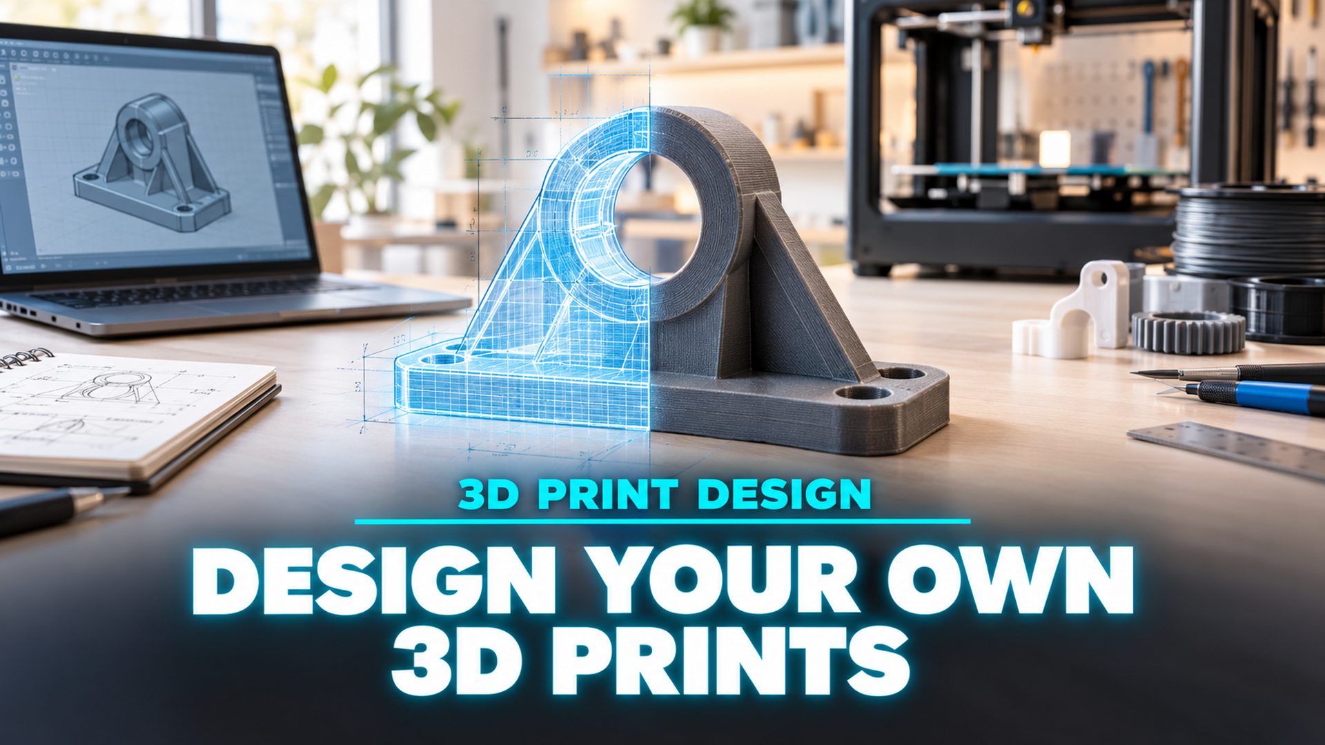
Designing a part that prints correctly on the first attempt comes down to three things: measuring the object it has to fit, choosing a modeling path that matches the geometry you need, and staying inside the wall, clearance, and overhang limits your printer can actually hold. This guide covers how to design your own 3D prints from that first measurement through to a sliced file, with the specific numbers that decide whether a part survives contact with the bed.
On This Page
- What Designing Your Own 3D Prints Actually Involves
- Start With the Idea: Measure the Real Object First
- Choose Your Design Path Before You Open Any Software
- Design Rules That Decide Whether It Prints
- Fix the Model Before You Export ItHOT
- Export, Slice, and Set Up the Print
- Your First Design: Three Projects and the Mistakes to Avoid
- Common Questions About Designing 3D Prints
- Start Designing Your Own 3D Prints Today
What Designing Your Own 3D Prints Actually Involves
Designing is a different job from downloading a file and pressing print. A downloaded model arrives as finished geometry. Someone else already decided where the walls sit, how thick they are, and which face rests on the bed. Designing is the stage where those decisions are still open, and every one of them changes how the part behaves once it exists.
Three constraints from the printer side shape all of it. They are physical, not stylistic, and no amount of modeling skill removes them.
- Nozzle diameter sets the smallest reliable feature. A standard 0.4 mm nozzle cannot lay down a wall thinner than the extrusion width it produces, so details below roughly 0.4 mm either vanish or print as a string.
- Layers stack, so the part is anisotropic. A print is strongest along the layer plane and weakest across it. A bracket loaded perpendicular to its layers can split along a layer line at a fraction of the force the same shape would take in solid plastic.
- Gravity decides which faces need help. Any surface that leans past a certain angle from vertical has nothing underneath it to support the next layer, and the printer will either bridge it badly or need dedicated support material.
None of this requires an engineering degree. It requires knowing the limits before you draw, because a model that ignores them gets redesigned after the first failed print, and the second attempt always costs more than the first. Most people looking into how to design 3D prints are after a starting point rather than a full CAD course, and the path they pick matters more than the hours they put in.
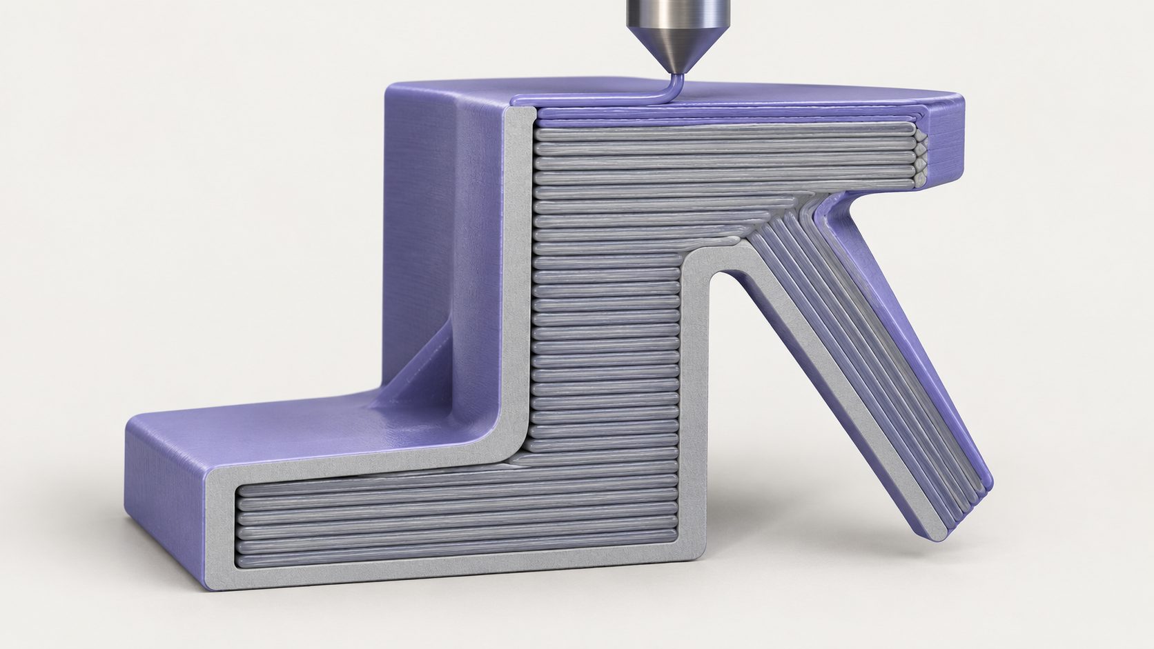
Nozzle width, layer stacking, and overhang angle are the three physical limits that shape every design decision downstream.
Start With the Idea: Measure the Real Object First
Every guide says to plan the design before modeling. Almost none say what planning means in practice, and the beginner threads on maker forums keep landing on the same failure: a part that fits nothing because nobody measured the thing it had to attach to. The modeling was fine. The number going into the model was wrong.
If a part has to fit something that already exists, that object is the specification. A digital caliper costs less than a spool of filament and settles questions that no amount of screen time can. Measure the mating surface, not the nominal size printed on a datasheet, because real objects carry paint, plating, and manufacturing variance that datasheets do not describe.
Write four things down before you open any tool:
- The mating dimension your part must match, measured at the actual contact surface.
- The clearance you intend to leave, as a number, not a feeling. It belongs in the sketch, not in your head.
- The load direction. Which way does force push on the part? That answer decides the print orientation later, and orientation is decided long before the slicer sees the file.
- A target size for the finished part, including how much of the build volume it may occupy.
Reddit answers treat this as the single biggest beginner mistake, and the reason is structural: a dimension error is invisible in the viewport. The model looks correct right up until it does not fit, and by then the design work is finished, sliced, and printed.
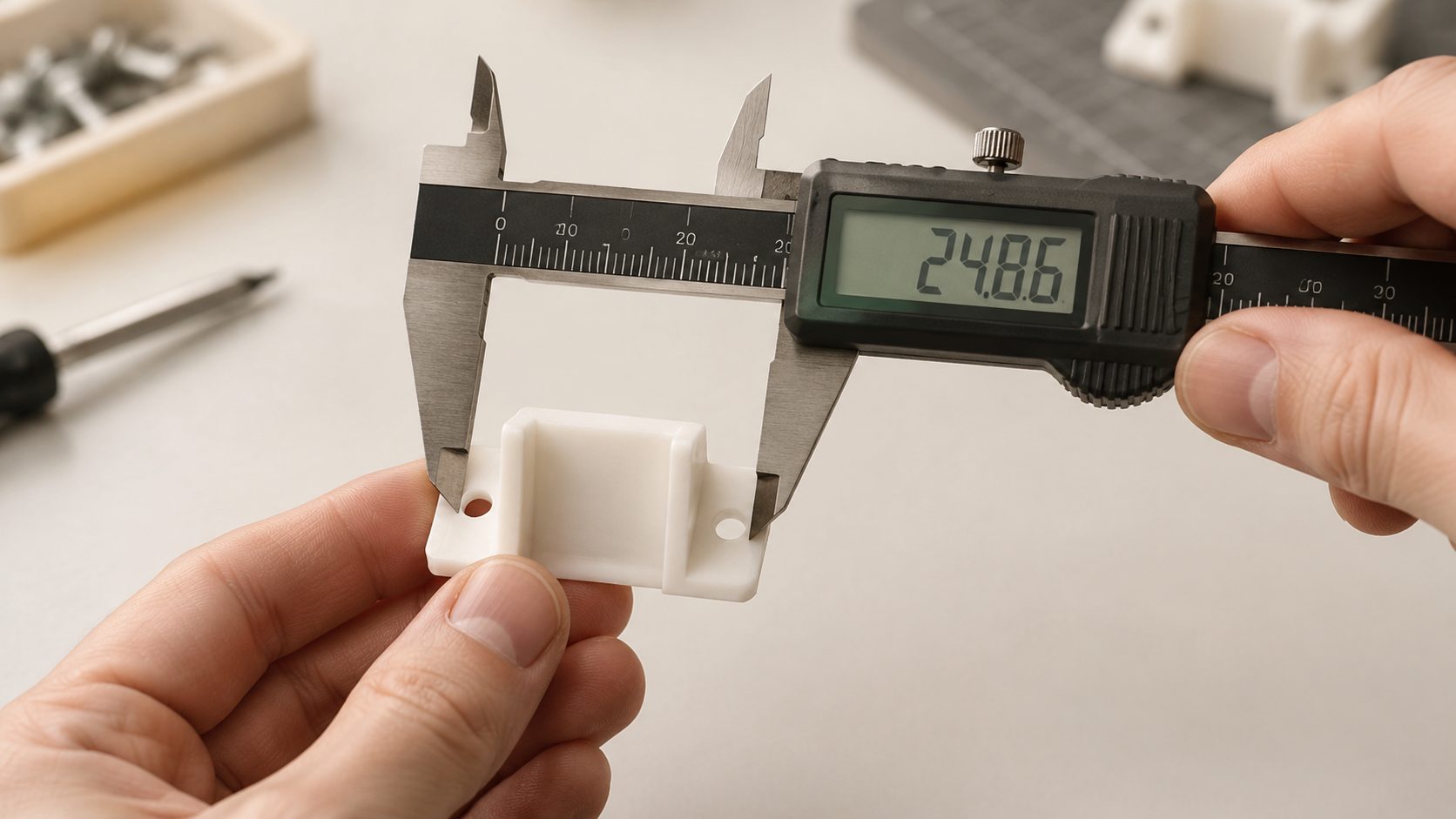
Measuring the real part first is the cheapest correction available in the entire workflow.
Choose Your Design Path Before You Open Any Software
Four paths lead to printable geometry, and they are not ranked against each other. Each one is the correct answer for a different kind of shape, and picking the wrong one is why a first attempt at how to design a 3D print can take a weekend instead of an afternoon.
Parametric CAD for Functional Parts
Fusion 360, FreeCAD, Onshape, and SolidWorks all work the same way underneath: you draw a 2D sketch, fully constrain it so no dimension is left ambiguous, then extrude, revolve, or loft that sketch into a solid. The payoff is that dimensions stay editable forever. When the caliper reading turns out to be 0.3 mm off, you change one number and the whole model rebuilds.
That is the reason functional parts belong here. A bracket, a drawer divider, or an enclosure is a series of defined dimensions, and a tool that stores those dimensions as parameters lets you iterate instead of redraw. If you are weighing options, the comparison of CAD software options for 3D printing covers the licensing and feature tradeoffs, and FreeCAD versus Fusion 360 breaks down the two most common starting points.
The cost is the learning curve. Sketch constraints are unforgiving at first, and an under-constrained sketch will happily produce a solid that is not the shape you thought you drew.
Browser-Based Direct Modeling for a First Win
Tinkercad takes a different approach: you place primitives and combine them with boolean operations, subtracting one shape from another until the result is what you wanted. There is nothing to install and no sketch solver to fight. For a measured part like a cable clip or a simple tray, it is the fastest route from idea to a file you can print.
The ceiling arrives quickly. Direct modeling has no history tree in the parametric sense, so a design with twenty interdependent dimensions becomes harder to revise than it would in CAD. Use it to learn how booleans and wall thickness behave, then move on when the shapes get complicated.
Sculpting and Mesh Modeling for Organic Shapes
Blender and ZBrush treat geometry as something you push and pull rather than dimension. Figurines, miniatures, characters, and anything with flowing curves come out better here, because there is no dimensional constraint to satisfy and no sketch to rebuild.
What you give up is precision. There is no dimension-driven workflow, so a sculpted part that must mate with something else needs a second pass to check fit. Sculpting is also the slowest of the four paths to a first result, which makes it a poor choice for a functional part regardless of how good the software is.
AI Generation From a Photo or a Text Prompt
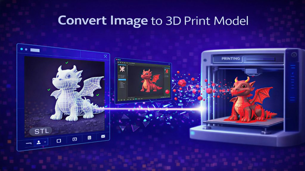
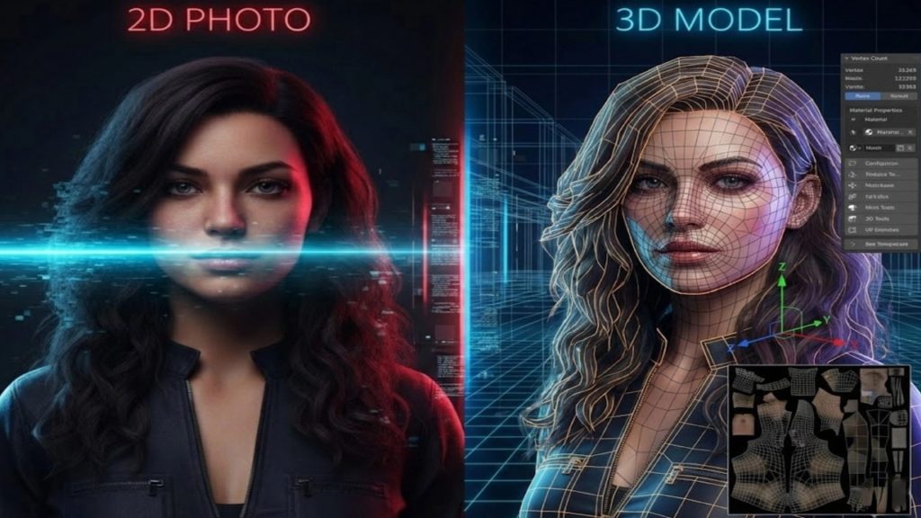
The fourth path skips geometry authoring entirely. Neural4D generates a 3D mesh from a single image or a text description, and the output arrives watertight and manifold, which means the surface closes on itself with no holes or open edges for a slicer to trip over. Export the STL and it goes straight into the slicer.
This is the path for readers who want a printable model without learning CAD. It is strongest for shapes that are hard to dimension in the first place: a decorative piece, an organic form, a replacement part for something you photographed. The AI for 3D printing overview covers where the workflow fits, and the guide to convert an image into an STL file walks through the photo-to-print case.
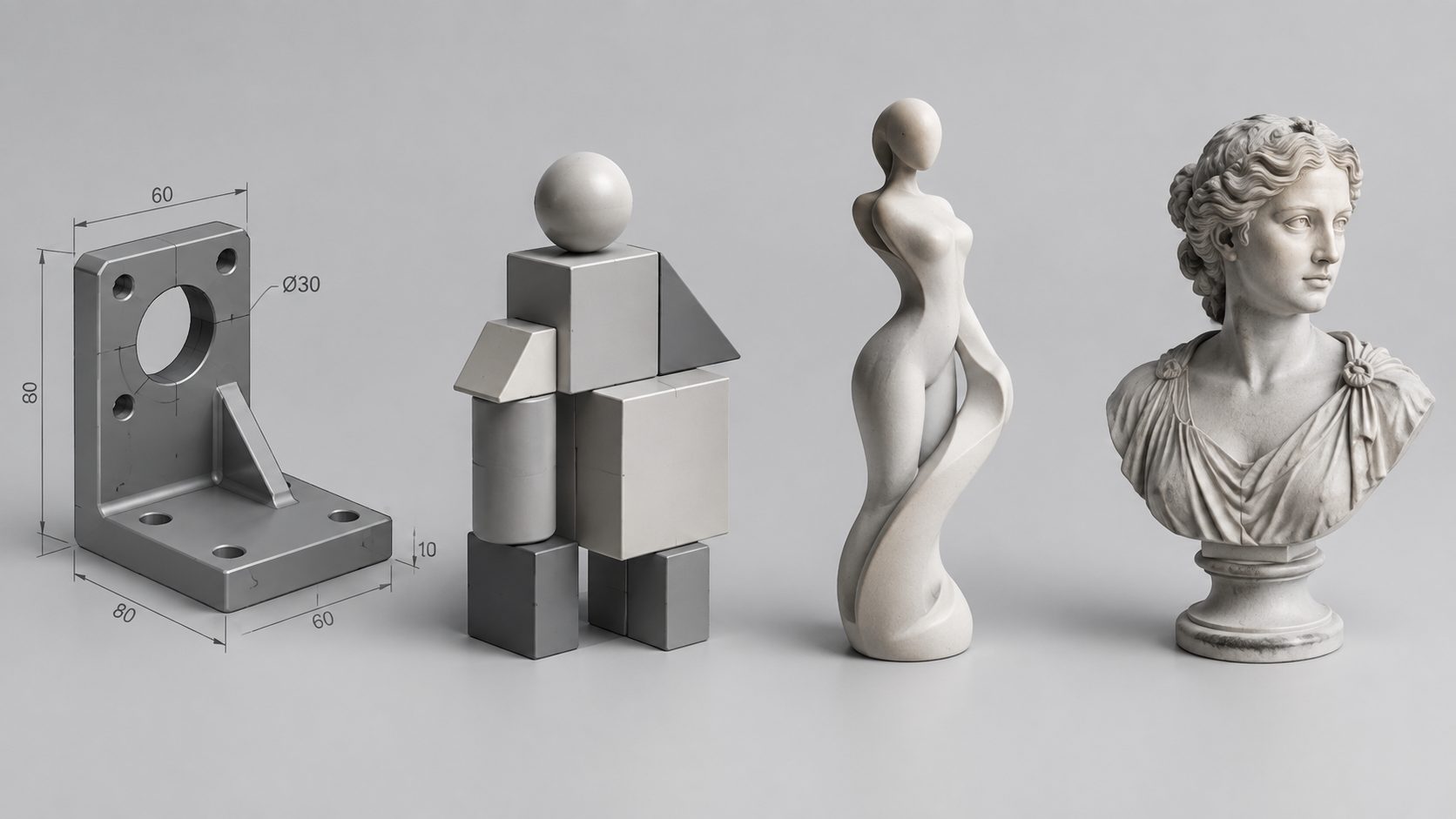
Each design path produces a printable file. The difference is how much dimensional control you need and how much time you have.
Match the path to the shape, and the table below settles most first-project decisions in under a minute.
| What You Want to Make | Recommended Path | Tools | Time to a First Part |
|---|---|---|---|
| A model from a photo or a text prompt | AI generation | Neural4D | Under 10 minutes |
| A bracket, clip, enclosure, or any measured functional part | Parametric CAD | Fusion 360, FreeCAD, Onshape, SolidWorks | 1 to 3 hours |
| A quick measured part with nothing to install | Browser-based direct modeling | Tinkercad | 30 to 60 minutes |
| A figurine, miniature, or organic decorative shape | Sculpting and mesh modeling | Blender, ZBrush | 3 to 10 hours |
The time column assumes you are learning the tool as you go. Once a path is familiar, a simple functional part takes minutes rather than hours in any of them.
Design Rules That Decide Whether It Prints
Learning how to design for 3D printing means internalizing a small set of numbers, and these are the ones that decide most outcomes. They apply at a 0.4 mm nozzle, which is the default on most FDM printers. Resin printers have their own limits and are noted where they differ. Treat the table as your starting calibration and adjust for your own machine once you have test prints to compare against.
| Parameter | FDM Value at 0.4 mm Nozzle | Why It Matters |
|---|---|---|
| Overhang angle | Up to 45 degrees from vertical without support | Past this angle the next layer has too little material under it and sags |
| Minimum wall thickness | 0.8 mm for floors and cosmetic walls, 1.2 mm for structural parts | The slicer needs two to three extrusion lines to build a wall that holds load |
| Minimum feature and gap | 0.4 mm | Anything smaller is thinner than the extrusion width and prints as a string or not at all |
| Hole shrinkage compensation | Add 0.1 to 0.3 mm to the modelled hole diameter | FDM holes print undersized because the extrusion pulls inward as it cools |
| Clearance for mating and moving parts | 0.2 to 0.4 mm on FDM, 0.1 to 0.2 mm on resin | Zero clearance fuses parts together; too much clearance makes a joint sloppy |
| Bridge span | 5 to 10 mm is reliable, sagging starts past roughly 20 mm | A bridge has no support underneath, so the plastic must cool before it drops |
| Layer orientation versus load | Align the load along the layer plane, never across it | Layer adhesion is the weakest direction in any FDM part |
| Bed contact face | At least one flat face, ideally a large one | Adhesion holds the part in place; a rounded bottom face will not stick |
Two of these catch beginners more than the rest. Hole shrinkage is invisible in a viewport because the model looks dimensionally perfect, and layer orientation is decided by how you rotate the part on the bed, which happens after the design is finished. Both are cheap to fix at design time and expensive to discover at assembly. Protolabs Network documents the full set of these constraints in its guide to designing parts for FDM 3D printing, and the fused deposition modeling reference explains why layer bonding creates the directional weakness that drives orientation decisions.
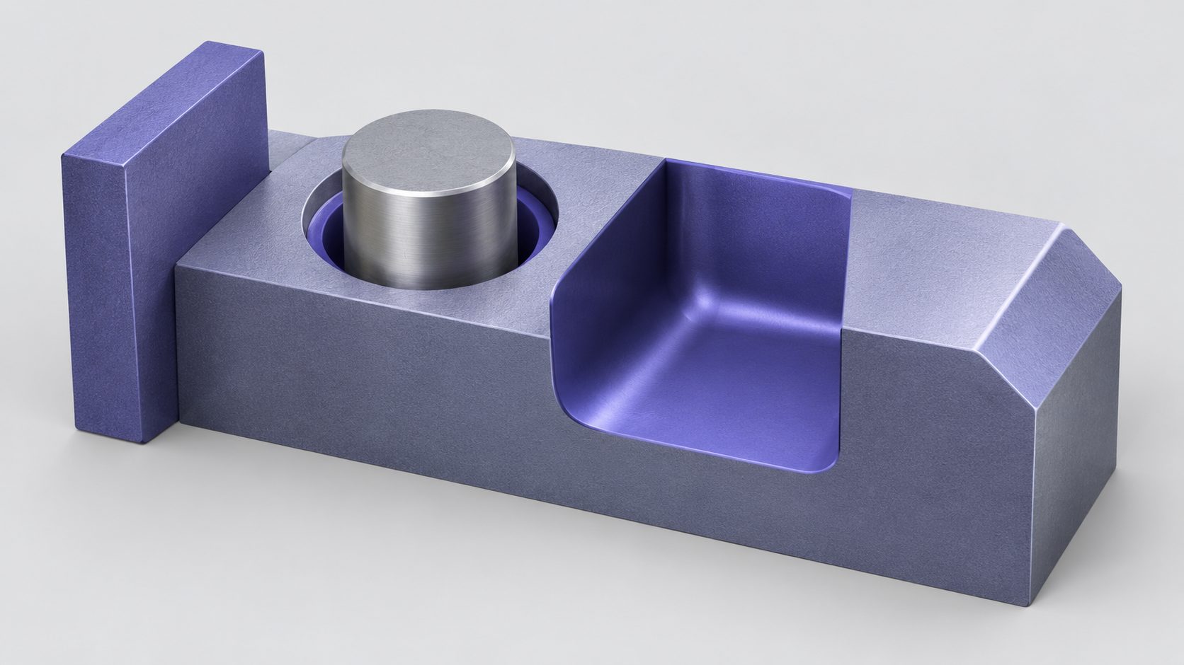
Wall thickness, clearance, fillets, and chamfers are the four geometry features that carry most printability decisions.
The six-point printability check
Run this before you export. Every item is faster to fix in the modeling tool than after a failed print.
- No overhang past 45 degrees from vertical unless you have planned support.
- Every wall at or above the minimum thickness for its role.
- Every hole compensated for shrinkage.
- Clearance set on any mating or moving part.
- At least one flat face that will sit on the bed.
- The mesh is watertight and manifold.
Fix the Model Before You Export It
Item six on that checklist is the one that sends prints back to the modeling stage. A non-manifold mesh has holes, flipped normals, or self-intersecting faces, and a slicer cannot tell inside from outside on a surface like that. The result is missing walls, walls with zero thickness, or a slice that stops partway through with an error about intersecting geometry.
Inspecting the mesh takes seconds in most tools. Look for open edges around the boundaries of a shape, faces that appear inside out when you enable backface display, and any surfaces that pass through each other. CAD-authored meshes need this pass because boolean operations and shelling are the two most common sources of broken geometry, and both are routine in functional part design.
Thin walls come next. A wall that measures below the minimum thickness in the design converts to a gap or a single fragile extrusion in the print, and the slicer preview will show it as a discontinuity rather than a solid surface. Whether a part is oversized and needs splitting is the third check: a model larger than the build volume has to become two or more pieces, which means designing connectors, pins, or locating features so the parts align after printing instead of relying on glue and hope.
Hollowing is the last consideration and it trades strength for material. A large solid part wastes filament and takes longer to print, but hollowing it removes the material that resists load across the layers. Keep solid walls where force goes and hollow only where the volume is cosmetic.
Meshes generated by Neural4D are watertight by design, which is exactly the point of the AI generation path: the repair pass this section describes is work N4D removes rather than work it creates. The same does not hold for hand-modelled geometry, so the check stays on the list for anything you build yourself in CAD or a sculpting tool.
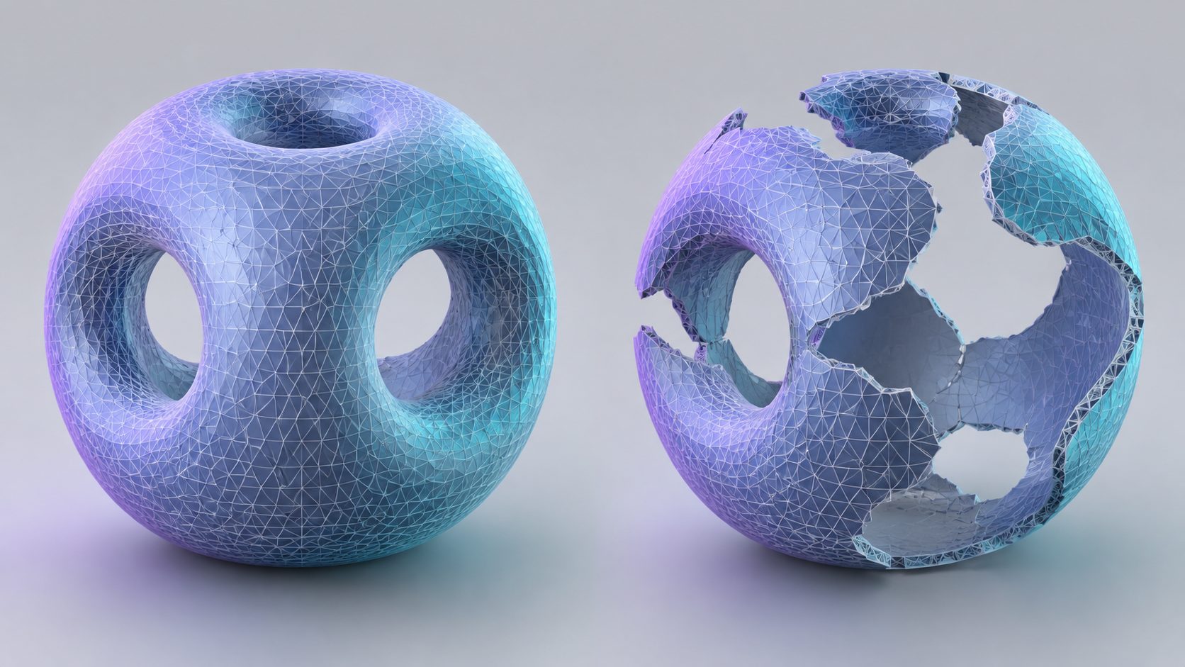
A watertight mesh closes on itself with no boundary edges. A non-manifold mesh gives the slicer no reliable inside or outside.
Skip the mesh repair pass entirely
Generate a watertight, manifold mesh from a single photo or a text prompt, then export STL and slice it.
Free users get 50 Power per week. No credit card required.
Export, Slice, and Set Up the Print
Export is where unit scale goes wrong. A model built in millimetres and exported in metres arrives a thousand times too small, and the mistake is invisible until the slicer shows a part the size of a grain of rice. Set the export unit to match the printer before you choose a format.
STL remains the safe default for a single-material print, though it carries geometry only and no units, which is part of why scale errors happen. 3MF stores units and multiple materials and is the better choice when a design has several parts or colour changes. OBJ is useful when the model carries texture information that matters for a decorative print. The preparing and exporting models for 3D printing walkthrough covers the settings on each, and colour workflows are detailed in the guide to coloring 3D models for printing.
Orientation on the bed is the design decision that happens last and matters most. Rotate the part so the load runs along the layer plane rather than across it, and so the largest flat face rests on the bed. If the strongest orientation creates an overhang you did not plan for, the fix belongs back in the model, not in a support setting that adds material you will cut away.
Slicer settings for a first print are forgiving. Start with a 0.2 mm layer height, drop to 0.16 mm if surface quality matters more than time, and set infill around 15 percent for PLA on a decorative or lightly loaded part. Tree supports detach cleanly from curved surfaces and standard supports are more predictable on flat ones. Before you slice, check the preview for wall count in the thinnest region: if a wall shows as a single extrusion line where the design called for two, the model is too thin and no slicer setting will fix it.
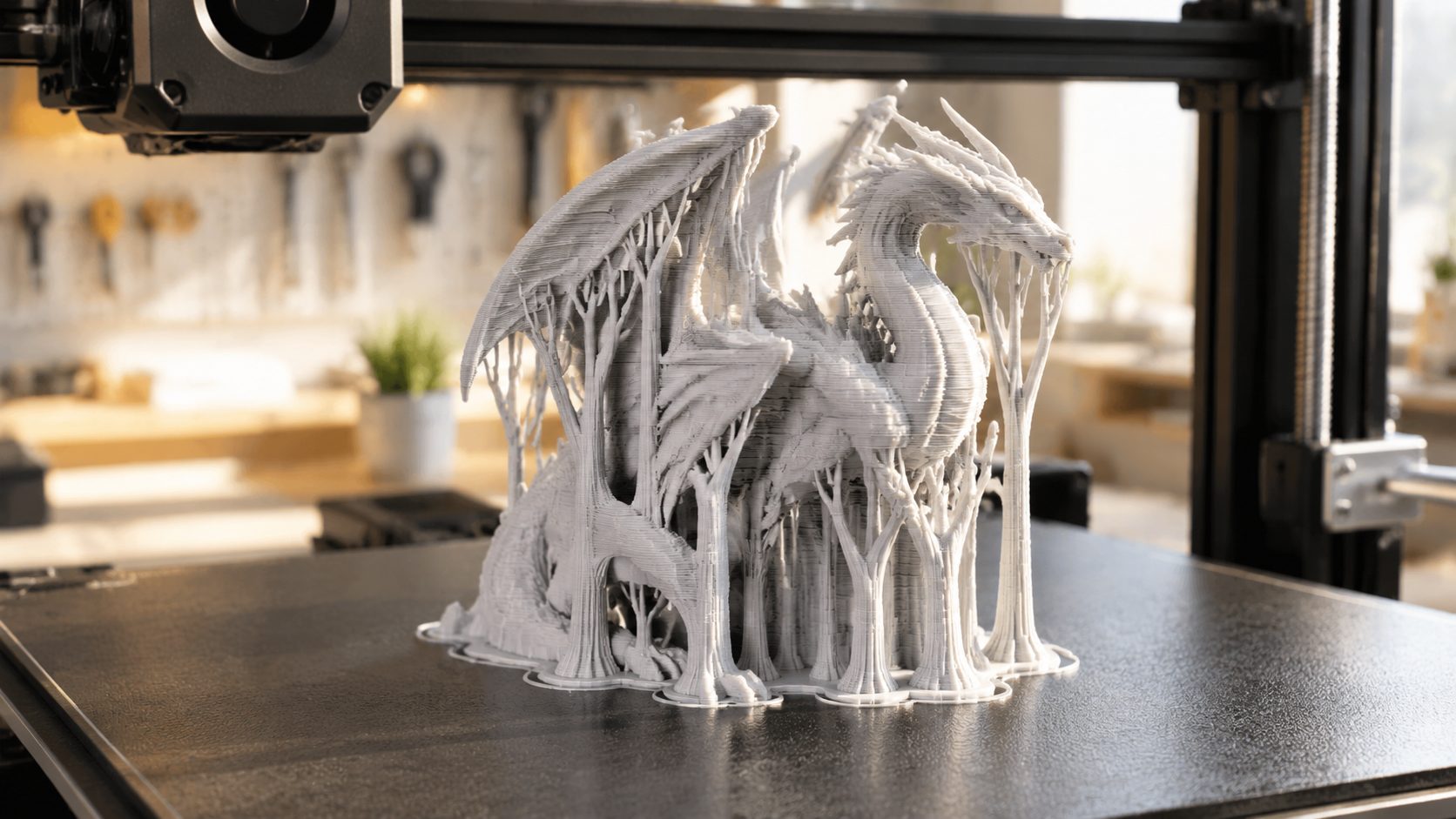
The slicer preview is the last place a design error is visible before the printer commits to it.
Your First Design: Three Projects and the Mistakes to Avoid
Pick the project that matches the path you chose. Each of these teaches one skill that carries into everything you design afterward.
A Cable Clip or Drawer Divider
The parametric path in miniature. Measure the cable bundle or the drawer gap with calipers, sketch a profile, and extrude it. The lesson is clearance: model the opening a fraction wider than the measured object, print it, and see what 0.3 mm actually feels like in your hand. Adjust the parameter and reprint. Nothing else teaches the relationship between a number in a sketch and a fit in the real world as quickly as this does.
A Phone Stand or Storage Tray
Direct modeling with primitives and booleans. Subtract a slot from a solid block, add a lip, and fillet the edges that will take handling. The lesson here is wall thickness: a tray with 0.6 mm walls feels like paper and a tray with 1.6 mm walls feels solid, and that difference is decided before slicing. If you want a shape that exists mainly to be handled, the guide to designing 3D printed fidget toys applies the same thinking to parts that exist for touch rather than function.
A Fidget Toy or Simple Figure
Sculpting or AI generation, depending on how much control you want over the form. A sculpted figure teaches mesh handling and how to check watertightness after brush work. A generated figure skips that entirely and moves straight to export, which makes it the faster route to a finished object but a slower route to learning geometry. Print either one with moving elements only after testing the clearance value on a small coupon first.
The mistakes that cost the most time
- Choosing an impressive first project. A multi-part articulated model teaches nothing except where your patience ends. Start with one shape that has to fit one real object.
- Skipping the calipers. Every dimension you guess is a reprint waiting to happen.
- Leaving a sketch under-constrained. The solid looks right and rebuilds into something else when you change one dimension.
- Treating export as the design step. Scale, orientation, and mesh integrity are design decisions. Export only records them.
- Designing line-to-line fits. A hole modelled at exactly the shaft diameter will not accept the shaft. Clearance is not optional.
- Ignoring non-manifold geometry. A slicer cannot repair a surface it cannot interpret, and the failure appears at slice time rather than at design time.
Common Questions About Designing 3D Prints
Q: Which 3D design software should a complete beginner start with, and what stays free?
Tinkercad is free, runs in a browser, and needs no install, which makes it the lowest-friction first tool. Fusion 360 has a free personal tier with a revenue cap and stores dimensions as editable parameters, so it is the better long-term choice if you intend to design functional parts. FreeCAD is fully open source with no tier restrictions at all. Starting with Tinkercad and moving to Fusion 360 or FreeCAD once you need a history tree is a common and reasonable sequence.
Q: Can AI design a 3D printable model without any CAD skills?
A purpose-built 3D generator can, and a general chatbot cannot. ChatGPT writes code and text, so asking it to design a part produces a script or a description rather than a mesh file you can slice. Neural4D generates actual geometry from an image or a prompt and exports STL, so the output goes into a slicer without an intermediate step. The practical limit is dimensional precision: AI generation is strongest for organic and decorative forms, while a part that must fit an existing object within 0.2 mm is still faster to build in CAD.
Q: Is there anything illegal to 3D print?
The printer is not the legal issue; the file and the use are. Firearms components are regulated or prohibited in most jurisdictions, and specific rules vary enough that there is no safe general answer. Beyond weapons, the two areas that catch makers are safety-critical parts (load-bearing components for vehicles, medical devices, or anything whose failure injures someone) and trademarked shapes. Printing a branded object for personal use is different from selling it, and generating a model from a photo of a branded product sits closer to the second case than most people assume.
Q: How do I test tolerances on my own printer?
Print a calibration coupon: a small flat test piece with a row of holes stepped in 0.1 mm increments and a matching row of pins. Print it once on your machine, then find the hole that the pin slides into with light friction. The difference between that hole size and the pin size is your machine’s real clearance for that material and layer height. Repeat it whenever you change filament brand or nozzle, because the number moves. Published values are starting points, not measurements of your printer.
Q: Can I design a 3D print without owning a 3D printer?
Yes, and the workflow is nearly identical. Upload the STL to a print service, which quotes by material and volume and ships the finished part, or use a local makerspace or public library with a printer on site. The one thing you lose is the feedback loop: without test prints you cannot calibrate clearance against your own machine, so you rely on the service’s published tolerances and add clearance conservatively. Design the part the same way, and confirm the service’s build volume before finalizing the size.
Q: What happens if my model is not watertight?
The slicer cannot determine which side of the surface is solid, so it may skip a wall, produce a zero-thickness shell, or refuse to slice with an error about intersecting geometry. Automatic repair tools fix simple holes but struggle with self-intersecting faces and inverted normals, and a repaired mesh sometimes loses detail in the process. CAD-authored models need the check because boolean and shell operations break surfaces routinely. Neural4D output arrives watertight and manifold by design, so the repair step does not apply to meshes generated there.
Start Designing Your Own 3D Prints Today
The workflow is shorter than it looks. Measure the object the part must fit, pick the modeling path that matches the shape, keep the walls, clearances, and overhangs inside the limits in the table, run the six-point check, and slice it. Every one of those steps is cheap to redo at design time and expensive to redo after a failed print.
For a first project, resist the urge to build something impressive. A cable clip that fits the cable you measured teaches more about how to design your own 3D prints than a multi-part model that fails for reasons you cannot identify. The path matters less than starting on something small enough to finish and adjust.
If learning CAD is the obstacle rather than the goal, start with generation instead. Describing a shape and getting a watertight mesh back puts a finished, printable object in your hands on the first attempt, and the design rules in this guide apply to that output exactly as they apply to anything you model by hand.
Turn an idea into a printable model today
Generate a watertight, manifold mesh from a photo or a text prompt with Neural4D, then export STL and print it.
Start Designing in Neural4D Studio
Built on research from Nanjing University, DreamTech, Oxford, and Fudan. Free users get 50 Power per week.
Share Your Creation
Tag @Neural4D and use #Neural4D to be featured on our channel.