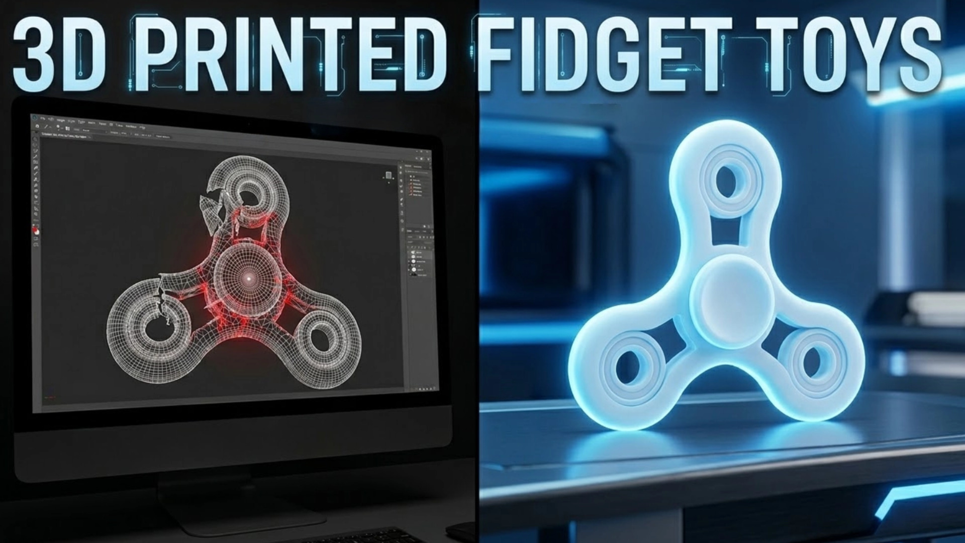
How to Design and Manufacture Flawless 3D Printed Fidget Toys
Quick Summary: Most free downloaded fidget models fail due to non-manifold geometry and bad tolerances. This guide breaks down how to use Neural4D AI to generate watertight base meshes from reference photos, establish perfect slicer settings for moving parts, and prototype custom mechanical designs without spending hours fixing broken CAD files.
Reality check: Most makers waste entire afternoons troubleshooting non-manifold edges and failed boolean operations before even starting a print. A watertight AI-generated base mesh eliminates that entire step.
There is nothing more discouraging than pulling a 12-hour print off the build plate only to find the internal slider is fused solid. Whether you are a hobbyist printing magnetic sliders or an engineer designing complex print-in-place mechanisms, you know that 3D printed Fidget toys require extreme precision. You are dealing with tight mechanical tolerances, moving hinges, and friction surfaces that demand clean geometry. Instead of fighting with complex organic modeling from scratch, modern makers are using spatial intelligence to skip the tedious base mesh creation phase. By leveraging image to 3D algorithms, you can upload a reference photo of a complex shape, generate a mathematically solid foundation within minutes, and focus your energy entirely on dialing in your slicer settings and mechanical joints.
- Part 1: Why Downloaded STL Files Ruin Print-in-Place Mechanisms
- Part 2: The Image-to-3D Workflow for Custom Maker Projects
- Part 3: Critical Slicer Settings for Mechanical Parts
- Part 4: Adding Magnets, Bearings, and Tolerances to Your Base Mesh
- Part 5: Post-Processing for the Perfect Tactile Feel
- FAQ: Troubleshooting Your 3D Printing Workflow
- Part 6: Conclusion – Start Printing Your Prototypes
Part 1: Why Downloaded STL Files Ruin Print-in-Place Mechanisms
The 3D printing community relies heavily on open-source repositories like Printables and MakerWorld. However, free online models are notorious for structural flaws. When an amateur designer uploads a file, they often merge complex boolean shapes without properly cleaning the topology. This results in non-manifold edges, inverted normals, and overlapping geometry that your slicer simply cannot interpret correctly. If you have ever wondered why seemingly simple prints fail halfway through, reviewing the hidden costs and mesh issues of free 3D models will quickly reveal the culprit.
When you attempt to print a complex mechanical toy with these hidden defects, the slicing software tries to guess how to fill the gaps. It might create unnecessary internal walls, skip crucial perimeters, or leave microscopic gaps that cause layer shifts. For static statues, you might get away with it. For mechanisms that rely on sub-millimeter clearances to slide or spin, a bad mesh guarantees a fused chunk of plastic.
To avoid wasting filament, you need a workflow that guarantees mathematically watertight geometry from the start. A clean mesh ensures that when you send the file to your slicer, the outer walls are continuous, the infill has a solid foundation to grip, and the dimensional accuracy remains intact throughout the entire print job. If you want to explore free 3D model design software, you need tools that prioritize volume and density over mere surface appearance.
Furthermore, relying on pre-made STLs limits your creativity. If you want to adjust the ergonomic curve of a slider to fit your specific hand size, modifying a dense, triangulated STL file in Blender or Fusion360 is a nightmare. The geometry breaks, the bevels fail, and you spend more time fixing the mesh than actually designing the toy. Building your own custom geometry from a clean slate is the only reliable path forward for predictable output.
Part 2: The Image-to-3D Workflow for Custom Maker Projects
Organic modeling in traditional software takes days. Pushing vertices to get the perfect ergonomic curve for a hand-held object is a massive time sink. The fastest way to prototype today is utilizing visual reference. You find a concept image online, snap a photo of a clay prototype you made by hand, or sketch a quick profile.
This is the key shift in the maker workflow: you are no longer modeling geometry. You are validating it. That alone removes the biggest bottleneck in mechanical prototyping.
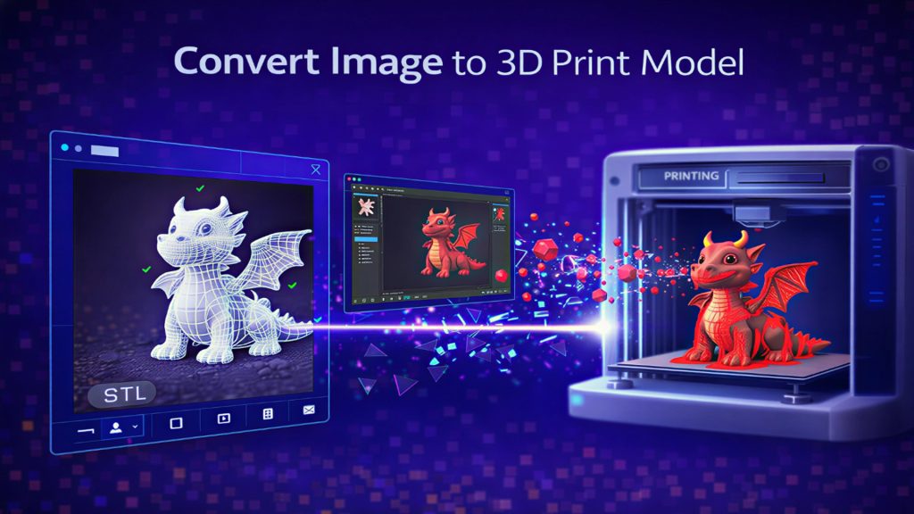
This is where the Neural4D Direct3D-S2 engine changes the game. Instead of starting with a primitive cube, you use that reference image. You upload the photo into the Neural4D studio, and the algorithm processes the spatial data. Within minutes, you get your base mesh. The system calculates actual depth and mass, meaning the resulting export is inherently watertight. You can literally convert an image to a 3D print model and immediately drop it into PrusaSlicer or Bambu Studio without requiring third-party repair tools to patch holes.
| Workflow Metric | Traditional CAD Workflow | Neural4D AI Workflow |
|---|---|---|
| Starting Point | Fixing broken, non-manifold STLs | Starting with a watertight base mesh |
| Time Investment | Hours of manual organic sculpting | Generating core geometry within minutes |
| Final Outcome | Trial-and-error prints and clashing boolean cuts | Predictable, first-print success |
You let the AI handle the complex exterior curves, and you use your engineering skills to handle the precise internal mechanics. It is a massive reduction in computational overhead for your brain. By splitting the workflow, you achieve results that would take veteran 3D artists days to complete. Utilizing the best image to 3D model AI provides a clean, non-manifold geometry ready for mechanical modification.
Upload a concept photo and generate a watertight, print-ready base mesh within minutes.
Generate Your Fidget Shell Now
Trusted by makers to generate watertight meshes that print right on the first attempt.
Part 3: Critical Slicer Settings for Mechanical Parts
Even with perfect geometry, 80% of failed fidget prints come from incorrect slicer settings. The model itself is rarely the only issue.
Even the most perfect watertight mesh will fuse together if your slicer settings are optimized for speed instead of dimensional accuracy. When dealing with print-in-place mechanisms or magnetic sliders, the physical reality of extruded plastic dictates your success. You cannot rely on default speed profiles.
First, address the “elephant’s foot.” The first layer of any print squishes into the build plate to ensure adhesion. If you are printing a slider, that horizontal squish will completely lock the bottom mechanism. You must use the Initial Layer Horizontal Expansion (or Elephant Foot Compensation) setting in your slicer. Set it to a negative value, typically around -0.15mm to -0.2mm, to pull that first layer inward and maintain your clearances.
Second, focus on wall ordering. For mechanical accuracy, always print the Outer Wall first. By default, many slicers print the inner walls and infill before the outer shell to hide seams. However, this pushes excess plastic outward, ruining your dimensional accuracy. Printing the outer wall first ensures the exterior dimensions of your joints and sliders are exactly what the geometry dictates.
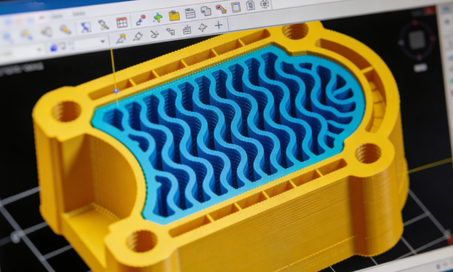
Finally, consider the weight and tactile feel. A hollow plastic shell feels cheap. Increase your wall loops to 4 or 5, and use a dense infill pattern like Gyroid at 40% or higher. This adds necessary mass to the object, giving it a satisfying inertia when spun or snapped. Cooling is another critical factor. If you are printing overhangs on a print-in-place hinge, your part cooling fan needs to run at 100% to solidify the plastic before it sags and fuses to the layer below.
Part 4: Adding Magnets, Bearings, and Tolerances to Your Base Mesh
Neural4D generates the beautiful, ergonomic exterior shell based on your image. But a mechanical toy requires specific hardware integration. Once you export your model from the studio, the real maker magic happens in your CAD software of choice, whether that’s Blender, Fusion360, or even directly inside modern slicers using negative volume modifiers.
Import the clean geometry. Because it is watertight, you can easily use boolean operations without the software crashing. If you are building a magnetic slider, you need to cut circular voids into the mesh. Measure your neodymium magnets with digital calipers. Add a 0.15mm tolerance to the diameter of your cut-out to ensure a snug press-fit without cracking the PLA layer lines. For instance, a 6mm magnet needs a 6.15mm hole.
For print-in-place hinges, clearance is everything. A standard, well-calibrated FDM printer needs exactly 0.2mm to 0.3mm of clearance between moving parts. Any tighter, and the layers will bond. Any looser, and the mechanism will feel sloppy and rattle. Because you learned how to convert an image to an STL file reliably, your base mesh won’t interfere with these precise boolean cuts.
If you are integrating a 608zz skate bearing for a spinner, the tolerance needs to be exact. A 22.2mm boolean cut usually provides the perfect friction fit for a standard 22mm bearing. Export the final modified STL, load it into your slicer, and hit print. By separating the organic design phase from the mechanical engineering phase, you drastically reduce your iteration time.
Part 5: Post-Processing for the Perfect Tactile Feel
The difference between a cheap plastic toy and a premium tactile experience often comes down to post-processing. Even with the best slicer settings, layer lines introduce friction. For sliders that rely on two flat surfaces sliding against each other, those layer lines act like tiny speed bumps.
Start by wet sanding the contact surfaces. Use 400-grit sandpaper, moving up to 800-grit, and finally 1200-grit. Wet sanding prevents the friction from melting the plastic and creates a glass-like finish. For magnetic sliders, this step is non-negotiable if you want a silent, snappy return.
After sanding, apply a dry PTFE lubricant to the friction tracks. Unlike oil-based lubricants, dry PTFE will not attract dust or degrade the plastic over time. It bonds directly to the sanded PLA or PETG, dropping the friction coefficient significantly. This transforms the grinding noise of raw 3D prints into a smooth, satisfying mechanical click.
FAQ: Troubleshooting Your 3D Printing Workflow
Why do my print-in-place parts keep fusing together?
This is usually caused by over-extrusion or an elephant’s foot on the first layer. Calibrate your extruder’s flow rate, ensure your first layer isn’t squishing too hard into the bed, and verify that your CAD model has at least a 0.2mm to 0.3mm clearance gap between the moving surfaces. Printing outer walls first also prevents dimension bloat.
Can I use generated models directly without editing?
Yes. The models exported from the Direct3D-S2 engine are mathematically watertight and can be dropped directly into a slicer. However, for mechanical toys, you will usually want to take the base mesh into a CAD program to add specific boolean cuts for magnets, bearings, or hinges.
What material is best for high-friction moving parts?
While PLA is great for fast prototyping, it deforms under heat and friction over time. PETG or ABS/ASA are much better choices for mechanical sliders or snap-fit joints due to their higher wear resistance, impact strength, and slight flexibility.
Part 6: Conclusion – Start Printing Your Prototypes
Building functional mechanical devices requires reliable geometry. When you eliminate the guesswork of broken meshes and non-manifold edges, the entire manufacturing process becomes predictable. By utilizing spatial intelligence to handle the complex organic shapes from your reference photos, you free up your time to perfect the clearances, dial in the slicer settings, and ensure the final physical object works exactly as intended.
The result: A design that prints cleanly, moves freely, and feels intentionally engineered rather than accidentally functional.
Stop fighting with tedious vertex pushing and start prototyping your custom 3D printed Fidget toys today with a workflow built for actual makers.
Upload an image and let the Direct3D-S2 engine generate the solid foundation for your next project.
Join thousands of engineers and hobbyists skipping the STL repair phase entirely.