How to Make iPhone Duo 3D Model: From Reference Photos to a Print-Ready Foldable
Quick Summary
- An iPhone Duo 3D model is two rigid phone shells joined by a working hinge, and the split between them drives every later decision.
- Glossy glass and a near-flat slab are the two conditions that reliably break photo-based reconstruction.
- Four to six reference views produce noticeably better geometry than a single hero shot of a thin, reflective product.
- Image generation covers the shells and their surface detail; the hinge, fold axis, and print gap stay manual work.
- N4D turns a set of product photos into a watertight mesh with clean topology, which is the part that has to survive both an AR viewer and a printer bed.
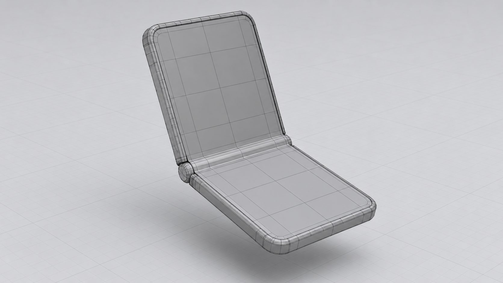
An iPhone Duo model is two rigid shells joined by a hinge, and that split decides everything downstream. Photo-based generation handles the shells and their surface detail well; the hinge, the fold axis, and the print gap are decisions you make afterward. Get how to make iPhone Duo 3D model geometry right and the same mesh feeds an AR viewer, a product render, or a printed folding replica.
Why a Foldable Phone Breaks Standard 3D Generation
The answer is to stop treating the phone as a single object. A foldable is a mechanical assembly: two display halves, a spine that rotates, and a gap that has to stay open through thousands of cycles. Apple builds that spine from a titanium hinge with more than 100 components, and the hinge cover itself is 3D printed from 100% recycled Grade 5 titanium. A single generated shell cannot express any of that, so the realistic target is two accurate shells plus a hinge you design.
Reference photos of a phone also fail for a physical reason. Glass reflects, and a reflection moves independently of the surface carrying it as the camera moves. Reconstruction software depends on a feature staying in the same place on the object across multiple frames, and a reflection never does. Clean glass also carries almost no matchable surface detail, so there is nothing for the algorithm to lock onto.
The second failure is flatness. Photogrammetry and multi-view generation both need depth variation to triangulate a point. A phone is close to a slab, which means its front and back are nearly coplanar and only the edge and the chamfer give reliable geometry. That is why phone scans tend to come back with a soft, inflated silhouette and mushy corners.
The useful split is between what generation solves and what you still build by hand.
| Part of the model | Where it comes from |
|---|---|
| Outer and inner shell surfaces | Generated from reference photos; this is what image to 3D is good at |
| Display bezels, camera island shape, button recesses | Generated, then checked against real dimensions |
| Surface material and finish | Generated as base color or PBR maps when you request textures upfront |
| The hinge and its internal gap | Manual. Generated meshes are single static shapes with no joint |
| Fold axis and the split between halves | Manual. This is a design decision, not a reconstruction output |
| Print clearance and wall thickness | Manual, and specific to your printer and material |
Step 1. Capture References a Generator Can Read
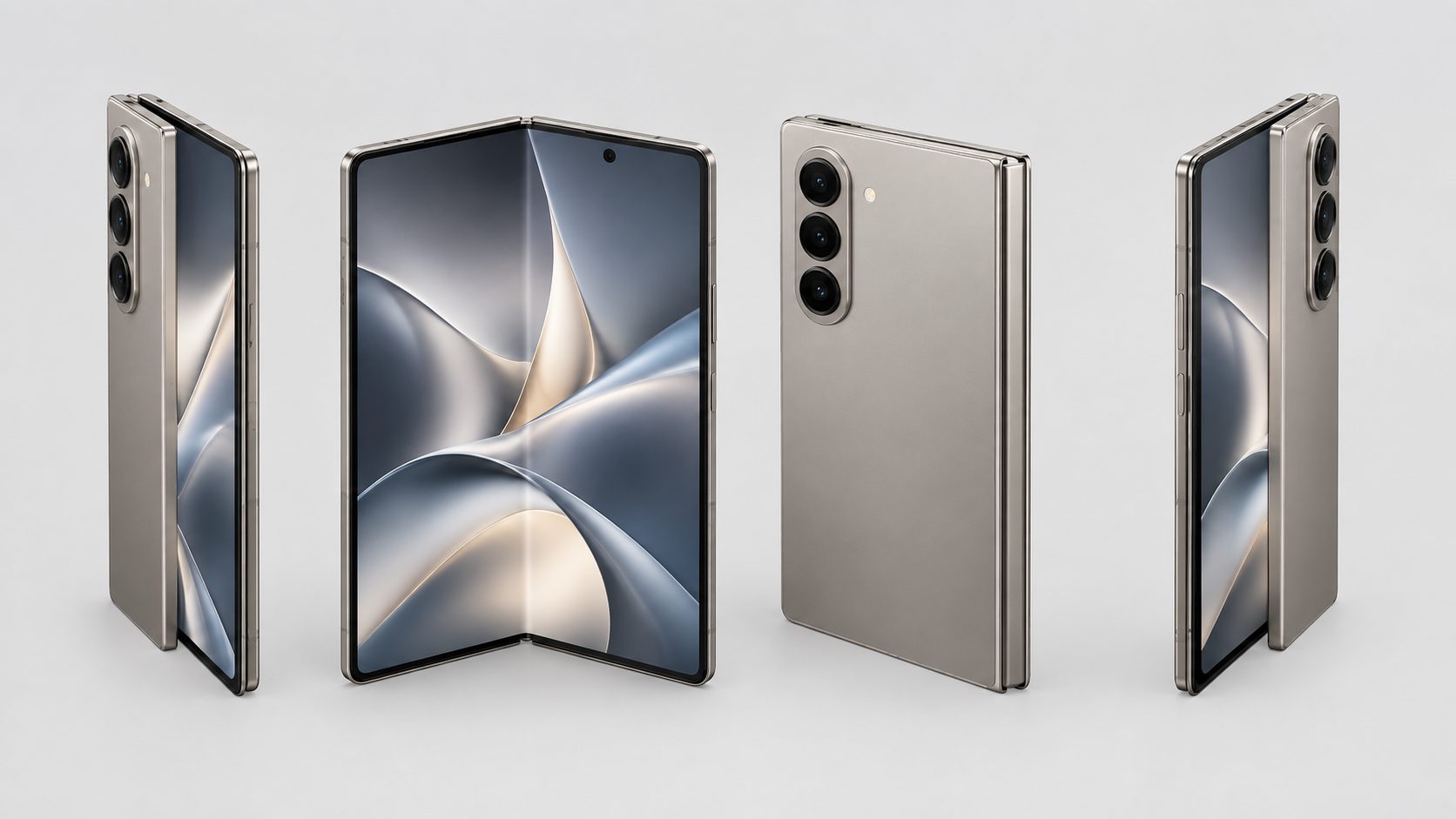
Reference quality sets the ceiling for everything that follows. Multi-view generators work from named view slots: front, back, left, right, top, and a three-quarter angle. One photo can work, but four to six views produce a visibly better result, because each additional angle resolves a surface the others could not see.
Keep the device still and move the camera around it rather than rotating the phone on a turntable. A turntable changes the relationship between the light and the object with every frame, and the algorithm reads that moving highlight as moving geometry. Walking around a stationary phone keeps lighting consistent, which is the single biggest quality improvement available at this stage.
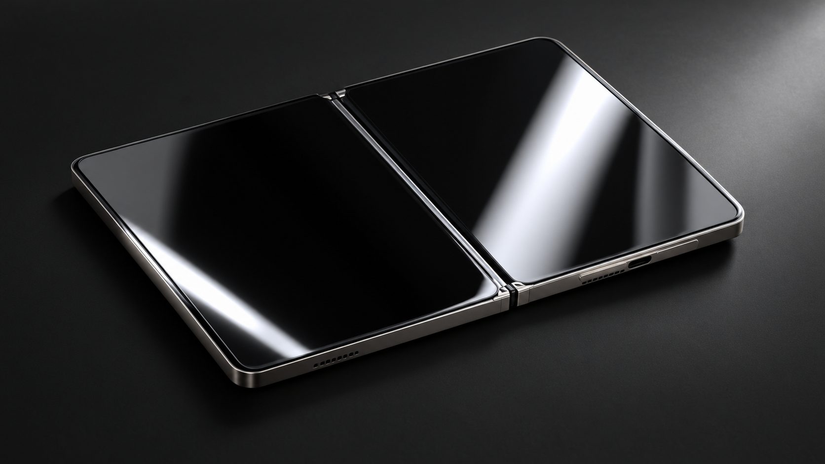
Shoot with the phone flat and unfolded if you want a straight shell, or fully folded if you want the closed silhouette. Shoot both states if you plan to model the fold, since an open photo tells you nothing about where the two halves meet when closed. Also capture a close pass over the camera island and the buttons, because those are the features a viewer notices first when the model is wrong.
Background matters more than it should. A busy surface gets reconstructed as part of the object, so place the phone on something plain and move anything reflective out of frame. Matte surfaces and soft, diffuse light reduce the reflection problem described above. If your only reference is a glossy press render, expect dents and a swollen edge, because the render’s own highlights will be baked into the mesh as dents and bumps.
Step 2. How to Make iPhone Duo 3D Model Geometry in N4D
Generation is where the shells appear. Open N4D Image to 3D, upload your reference set, and decide on textures before you start the run, because that choice is configured upfront rather than triggered afterward.
A base mesh without textures arrives in roughly 90 seconds. Select standard textures or full PBR maps and the same run needs two minutes or more, since base mesh and materials are computed together in one pass. That single decision is worth making deliberately: a matte material reads better on a phone body than a default glossy finish, and PBR maps give you separated metal and glass regions you can reuse in a renderer.
Inspect the result in the viewer before you accept it. Rotate to the underside and the back, and check three things: whether the panel edges are straight, whether the camera island kept its shape, and whether the shell is closed. A watertight, closed mesh is the property that lets the same file go to a slicer without repair work.
If a run comes back soft or asymmetric, change the input rather than re-rolling the generator. Swap a glossy reference for a matte one, add the missing view, or crop a distracting background. The one-click regenerate option is useful for comparing two prompts, not for rescuing thin references.
The Pro plan raises throughput, and free accounts include 50 Power per week, which is enough to work through a few reference sets before you commit to a pipeline.
Step 3. Refine the Hinge and the Proportions
Generated geometry gives you the shape of a phone. It does not give you a folding mechanism, because the output is a single static mesh. Everything in this step is manual, and it is where most of the model’s credibility comes from.
Start by splitting the shell along the fold axis. Most builders generate the open state once and mirror the half, which guarantees the two sides match. If you need the closed state as well, generate it separately from folded references instead of trying to bend the first mesh into a new shape.
Next, give the halves something to rotate around. A printed phone typically uses a pin running through a barrel, or interlocking teeth along the spine. Either works; the choice changes the gap you need, not the workflow. Keep the barrel geometry simple, because a complex hinge with fine features is where a print fails first.
Scale is the decision that catches people out. Apple’s published dimensions put the Duo at 164.6 mm by 117.8 mm open, 84.6 mm by 117.8 mm closed, and 5.2 mm per half. Those numbers give you a real target: model at 1:1 if the print is a size reference for a case or a mount, and model at a larger scale only if you want a display piece, because shrinking a finished model also shrinks the internal gaps until the joint fuses.
Finally, set wall thickness against your process. FDM needs at least 0.8 mm, which is two 0.4 mm perimeters, and 1.2 mm to 1.6 mm is a safer range. Resin holds thin walls better, with 0.5 mm as a floor and 1.0 mm recommended. Below those numbers a shell prints with holes or tears at the fold.
Step 4. Export GLB for AR or STL for Printing
The export follows the destination, and there are only two realistic destinations for a phone model. Pick one before you export, because the two formats carry different things.
| Destination | Format | What carries over | What to watch |
|---|---|---|---|
| AR viewer, web, or game engine | GLB | Mesh plus material and texture data | Keep the triangle count inside your viewer’s budget |
| 3D printer or slicer | STL | Geometry only, no color | Export a closed mesh, or repair it before slicing |
For a single product asset in a web AR viewer, a GLB in the 10,000 to 50,000 triangle range is a safe target. Google’s guidance for its own AR formats sits under 12,000 polygons, and Adobe Aero advises under 15,000, while heavier viewers tolerate 100,000 across a whole scene. A decorative phone model with an empty interior can sit comfortably in that band once you decimate the hidden surfaces. Our walkthrough on opening a GLB in a browser viewer covers how the file behaves once it is live, and converting an image to GLB covers the generation side of the same format.
If the destination is a printer, export STL and accept that color does not come with it. Single-material prints carry shape and nothing else, which is fine for a mockup and wrong for a display piece. Our guide to turning an image into an STL file covers the conversion path in more detail, and preparing a model for 3D printing covers the checks worth running before a slicer ever sees the file.
Turn your reference photos into a mesh
Generate a watertight, textured shell in N4D, then take it into the viewer or the slicer.
Free accounts include 50 Power per week.
Step 5. Print a Folding Version That Moves
A folding print lives or dies on one number: the gap between the moving parts. Get it right and the hinge works off the plate. Get it wrong and you have a solid brick with a decorative seam.
For FDM, the practical clearance range is 0.2 mm to 0.4 mm. PLA sits near the tight end at around 0.25 mm, PETG needs closer to 0.35 mm because it strings, and a pin-to-barrel joint is usually comfortable between 0.2 mm and 0.3 mm. Resin printing has no equally reliable published figure for print-in-place joints, so treat clearance as something you test rather than assume.
Two Failure Modes Worth Designing Around
The first is elephant’s foot, the slight flare where the nozzle squashes the first layers. It expands material into the gap you carefully designed and can weld a joint closed. Most slicers compensate for it, and a starting value between 0.1 mm and 0.2 mm is reasonable. The second is scaling: a joint that moved at full size can fuse at 60 percent, because the internal gap shrinks with everything else while the printer’s own accuracy does not improve. If you want a smaller phone, scale it before you size the hinge, not after.
Make the vertical gap a whole multiple of your layer height so the slicer places a clean boundary there. At 0.2 mm layers, a 0.4 mm vertical gap aligns exactly with two layers and prints more predictably than a 0.3 mm gap that the slicer has to approximate.
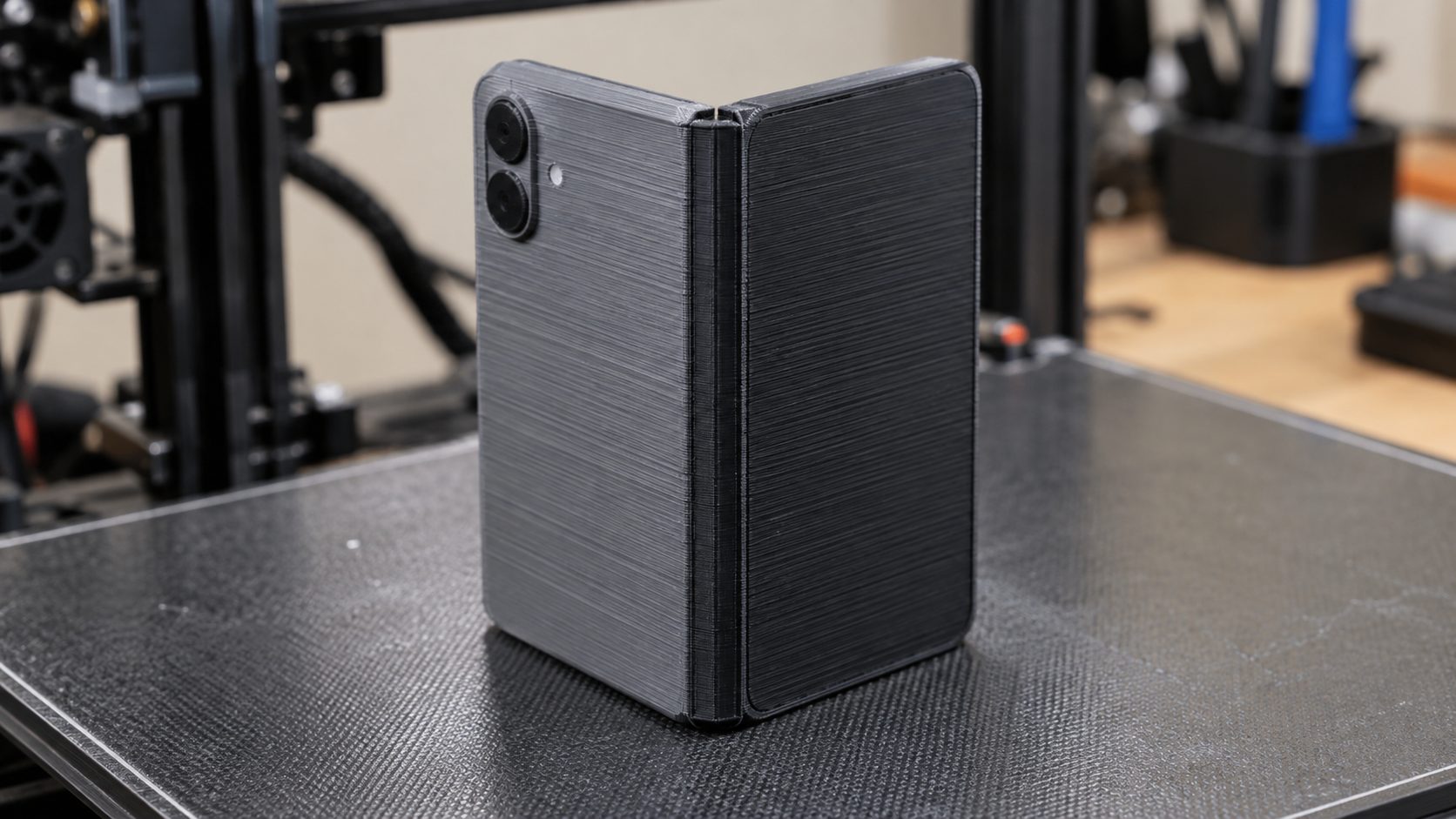
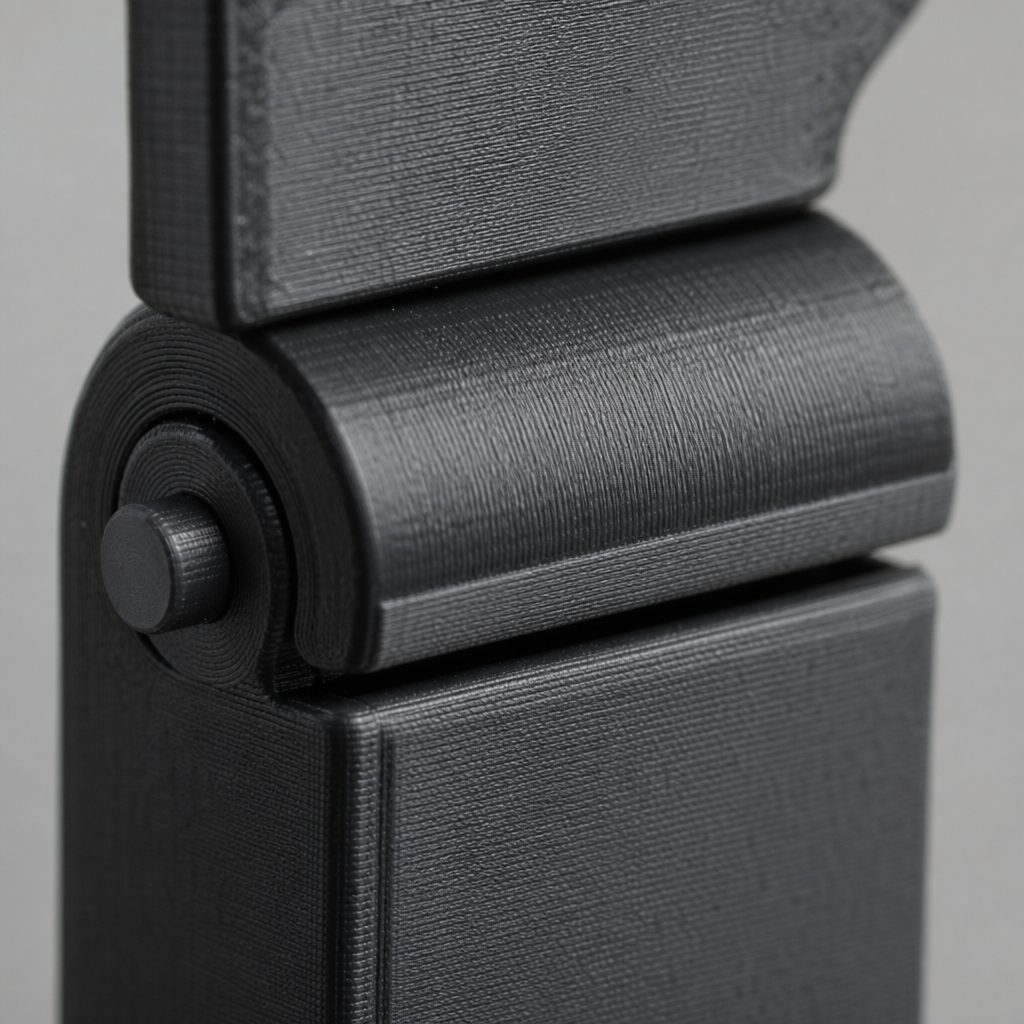
Print the two halves as separate parts for a first attempt. A two-part print with a filament pin is more forgiving than an interlocking print-in-place hinge, and it lets you check the fold before you commit to a single-piece design. If you later want to remove the assembly step, the joint principles in our guide to designing print-in-place joints that actually move apply directly to a phone spine.
Where N4D Fits in a Hardware Modeling Workflow
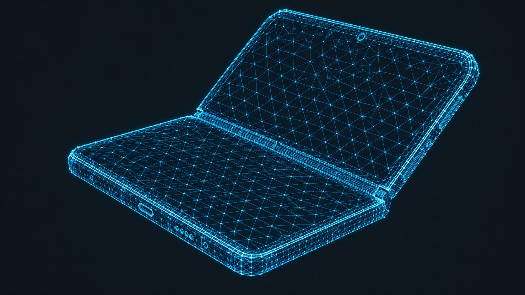
Be precise about the boundary, because overselling it wastes your time. N4D (Neural4D) reconstructs geometry from photos, and it does that job well on the parts of a phone that are genuinely hard to model by hand: curved glass transitions, the camera island, and the fine relief around buttons and ports. Its output is a watertight mesh with clean topology, which is the property that matters when the file goes to a slicer or an engine.
What it does not do is produce a mechanism. A generated mesh has no joint, no axis, and no clearance, so the hinge remains parametric CAD work. That division is normal in product prototyping: generative tools handle organic surface detail and CAD handles the moving assembly. If you also need a conversation-level pass on proportions or materials before export, N4D-2o handles natural language edits, and it works only on models that N4D-2o itself generated.
The honest tradeoff is control. Hand-modeling a phone in CAD gives you exact dimensions everywhere, at the cost of hours on surface detail. Generating from photos gives you the surface in about the time it takes to brew coffee, at the cost of needing to verify the dimensions you care about and to build the hinge yourself. For a mockup, a render, an AR asset, or a case-fitting check, that trade is usually worth taking.
Printing a Replica: What Is Actually Allowed
A phone is a trademarked and design-patented product, and the rules differ from what most makers assume. Two separate bodies of law apply, and they treat personal use differently.
Trademark law is the more forgiving of the two, because it requires use in commerce. Printing a phone shape for yourself generally is not trademark infringement unless you reproduce the marks or the trade dress, which in practice means keeping logos off the model. That is also why brand-neutral dummy models are the norm in this space.
Patent law has no such escape. A design patent runs 14 to 15 years and grants protection for the ornamental appearance of an object, and as legal commentary on 3D printing and product repair notes, there is no personal-use exemption for patent infringement. A replica of a patented ornamental design can infringe whether you print one or one thousand.
Selling is where the line becomes unambiguous. Commercial exploitation of a trademarked or patented product without authorization risks civil damages, and modifying the design does not help if the overall visual impression stays similar. The live example is Pop Mart’s action against Bambu Lab over user-uploaded character models on MakerWorld, which shows that platforms are now treated as part of the distribution chain rather than neutral hosts.
For a personal mockup, a case-fitting test, or a visualization asset, the practical risk is low. For anything you list for sale, use your own industrial design language rather than a recognizable product silhouette.
Common Questions About iPhone Duo 3D Models
Q: Can I generate both halves of the phone in one pass, or do I need two generations?
One generation covers one shell. In practice you generate the open phone once and mirror that half to build the second side, which guarantees the two halves match and keeps the fold axis symmetrical. Generating each half separately from different photos introduces small differences in curvature and thickness that show up as a mismatched seam once the parts are joined.
Q: What if my printed hinge fuses solid and will not move?
Work through three causes in order. First check elephant’s foot compensation and raise it toward 0.2 mm. Second, confirm the vertical gap is a whole multiple of your layer height, since an approximated gap can bridge. Third, check the scale: if you printed below roughly 70 percent of the modeled size, the joint has probably closed up and the model needs the hinge resized rather than reprinted. Force the joint by hand before you reprint, because a hinge that moves stiffly is usually fine after a few cycles.
Q: How accurate is a 3D-printed phone mockup compared with the real device?
Expect plus or minus 0.1 to 0.2 mm from resin, and 0.3 to 0.5 mm from FDM. Overall dimensions are rarely the problem, since the mesh can be dimensionally exact while the print drifts. The features that matter are the mating ones: a port or camera opening that lands half a millimeter off will not accept a cable or a lens, so check those against calipers rather than trusting the outer silhouette.
Q: Can I sell prints of a phone model I generated myself?
Generating the mesh yourself does not change the position, because the restriction attaches to the product’s protected design rather than to who produced the file. Selling is the clearest line: unauthorized commercial exploitation of a trademarked or design-patented product carries real exposure, and a modified silhouette still infringes if the overall visual impression is similar. Sell your own industrial design instead of a recognizable product shape.
Q: Why do glossy phone renders come out with dents and melted edges?
The generator read the reference’s highlights as surface shape, so a specular streak becomes a dent in the mesh. The tell is damage that follows the reflection pattern rather than the object’s real geometry. If you cannot reshoot, matte the device or the render with a temporary matting spray, which sublimates on its own after roughly 30 minutes, and use diffuse lighting with no hard source aimed at the glass.
Start From a Photo, Not a Blank Canvas
The shells are the slow part of modeling a phone by hand and the fast part when you generate them. Once you know how to make iPhone Duo 3D model geometry that holds up, the remaining work is a hinge, a clearance value, and a decision about scale, which is an afternoon rather than a week.
Load four to six clean references, generate the shell, and check the camera island before you move on. That first result tells you whether your photography or your prompt needs attention, and either way you have a usable mesh in minutes rather than hours.
Start from a photo, not a blank canvas
Upload a reference set and get a watertight, textured phone shell you can export as GLB or STL.
No modeling experience required. 50 Power per week on the free plan.