
How to Make a 3D Printed Stamp for Paper
Learning how to make a 3D printed stamp for paper starts with two checks: the raised areas must touch the paper evenly, and the artwork must transfer in the right direction. Start with a mark that makes a mirror error obvious. For this stamp, the paper should show a right-pointing arrow with a dot above its left side. Look straight at the raised face in CAD and you should see a left-pointing arrow with the dot on the right. Coala can build the stamp from those dimensions and export an STL. A test impression tells you how the printed surface, ink, and paper work together.
What You Need for a 3D Printed Ink Stamp
This example is a small relief stamp for paper tags and other flat paper projects. You need Coala in CAD mode, a slicer with a layer preview, an FFF printer that supports your chosen flexible filament, an ink pad for paper, and a few scraps of the stock you plan to stamp. The example STL is a flat stamp plate. If you want a larger grip, attach a flat backing block or a simple handle to the printed plate. Keep the plate seated flat so it does not rock under pressure. Use a material and build surface combination approved for your printer.
Flexible filament such as TPU is a practical starting point for a direct printed ink stamp. Prusa’s stamp guide recommends a soft material with a slightly porous surface that holds ink, and advises against PLA for the working face. If you only have rigid filament, you can use it to check size and orientation, then decide how to make the working face. In the same tests, a smooth build sheet gave a cleaner impression than satin or textured sheets, which could leave blank spots. Choose the printing profile from the printer and filament guidance for your setup.
Step 1. Design the Mark as It Should Appear on Paper
Sketch the finished impression first. Draw a right-pointing arrow and put a dot above the tail on the left. Keep that sketch next to the printer so you can use it to check the slicer and the first ink impression. The dot gives you a second orientation cue. It should stay above the shaft throughout the mirror operation.

Use a single left-to-right reflection while keeping the top edge fixed. If you rotate the artwork instead, the arrow may point the right way while the dot ends up below it. For the prompt below, the CAD coordinates already describe the mirrored face. Keep that orientation when you bring the STL into the slicer.
The example uses a 30 × 24 mm base, a thick arrow shaft, and a separate 4.4 mm dot. With wide shapes and an open gap between them, a missing feature is easier to spot in the toolpaths and on paper. For your first print, start with a similarly simple mark. Add finer details once you know what your printer and ink can reproduce.
Step 2. Model the Raised Stamp Face in Coala
Open Coala, N4D’s AI CAD agent, and start a CAD task. Describe the base and each piece of raised artwork. The example places the base between Z=0 and Z=4 mm and the relief tops at Z=5.5 mm. Starting the raised features slightly inside the base gives the union an overlap while leaving 1.5 mm exposed. Copy this example prompt or adapt it to a simple mark of your own.
Create one solid CAD model in mm for an ink stamp face. Base: 30 x 24 x 4, from (0,0,0) to (30,24,4). Viewed from +Z with +X right and +Y up, raise a left-pointing arrow on the top using these XY vertices in order: (5,10), (13,5), (13,8), (24,8), (24,12), (13,12), (13,15). Add a raised circle centered at (21,18) with radius 2.2. Both features extend from Z=3.8 to Z=5.5. Boolean-union them with the base. Keep the bottom and relief tops flat. No text, border, or handle. Export STL.
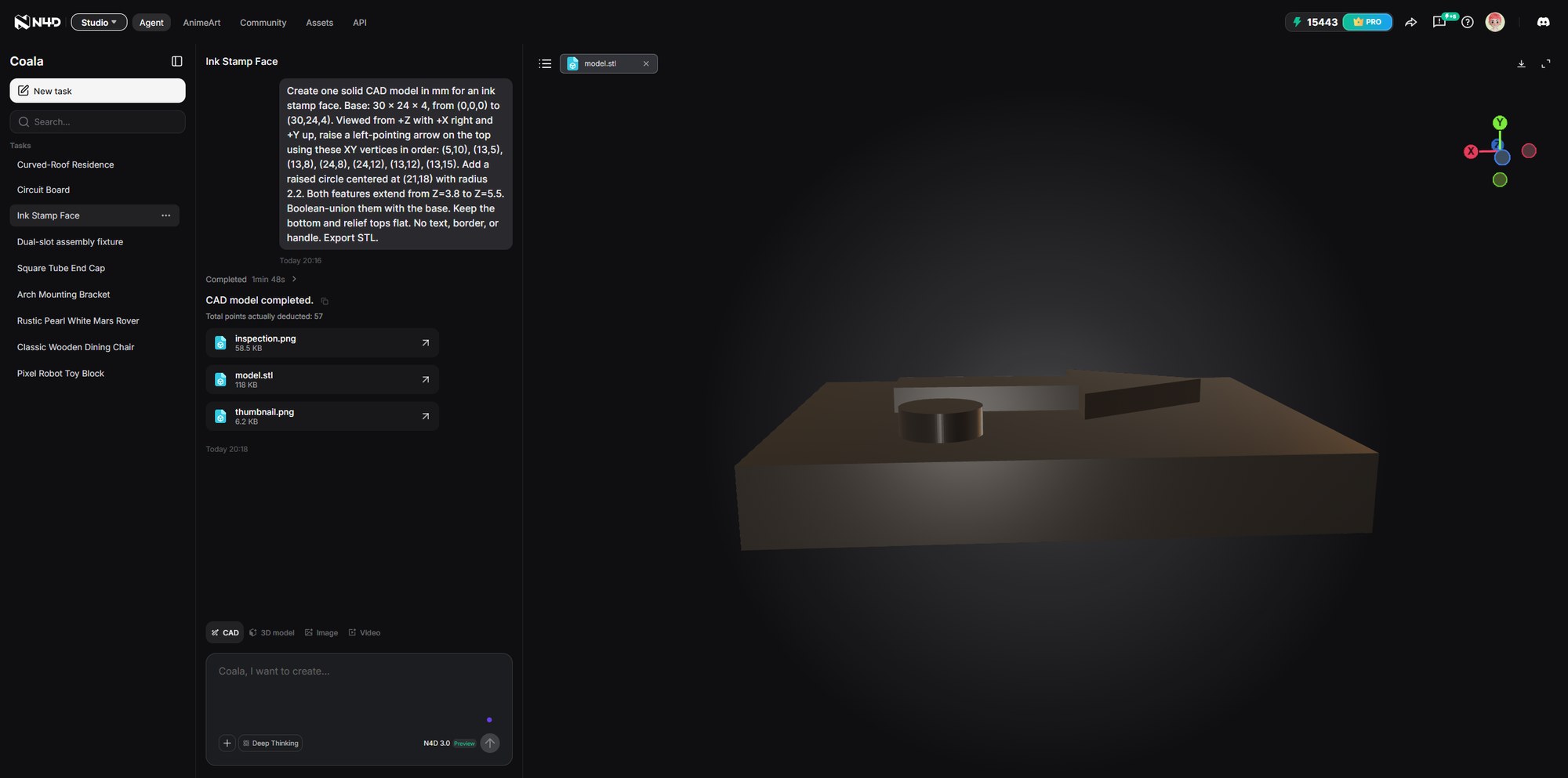
model.stl. The preview is angled. Check the arrow and dot from directly above the raised face.After generation, look straight at the raised face with the top edge oriented as in your sketch. Then export the STL and open it in a viewer or slicer that can display dimensions. Check these targets against the exported file before you commit to a print.
| Check | Expected geometry |
|---|---|
| Overall size | 30 × 24 × 5.5 mm at the intended millimeter scale. |
| Raised face | Flat artwork tops at the same height, 1.5 mm above the 4 mm base. |
| Orientation | Arrow points left in the face-on view with the top edge up. The dot is above the shaft on the right. |
| Geometry | The arrow and dot are raised from the same plate. Their tops are distinct. The model is one solid, with a flat underside. |
In the exported example STL, the base measured 30 × 24 × 4 mm. Both contact surfaces were flat at Z=5.5 mm, so the arrow and dot each rose 1.5 mm above the base. Viewed from +Z with +X to the right and +Y up, the arrow pointed left and the 4.4 mm dot sat at (21, 18), above and to the right of the shaft. The mesh formed one connected, closed piece. The intended paper impression is a right-pointing arrow with the dot on the upper left. Check that impression on scrap paper after printing.
If the face is reversed, correct the mirror once and recheck the dot as well as the arrow. If a feature is disconnected, the overall size alone can still look right. Inspect the model from the side and in the slicer layer preview. When the file differs from the specification, refine the prompt or correct the geometry in a CAD editor and re-export before printing.
Step 3. Slice and Print a Test Stamp
For this simple plate, begin with the flat underside on the build plate and the artwork facing up. This lets the raised features grow from a supported base. Use a flexible-filament profile intended for your printer and filament. Check the spool or printer documentation for the nozzle temperature, build surface, and release instructions.
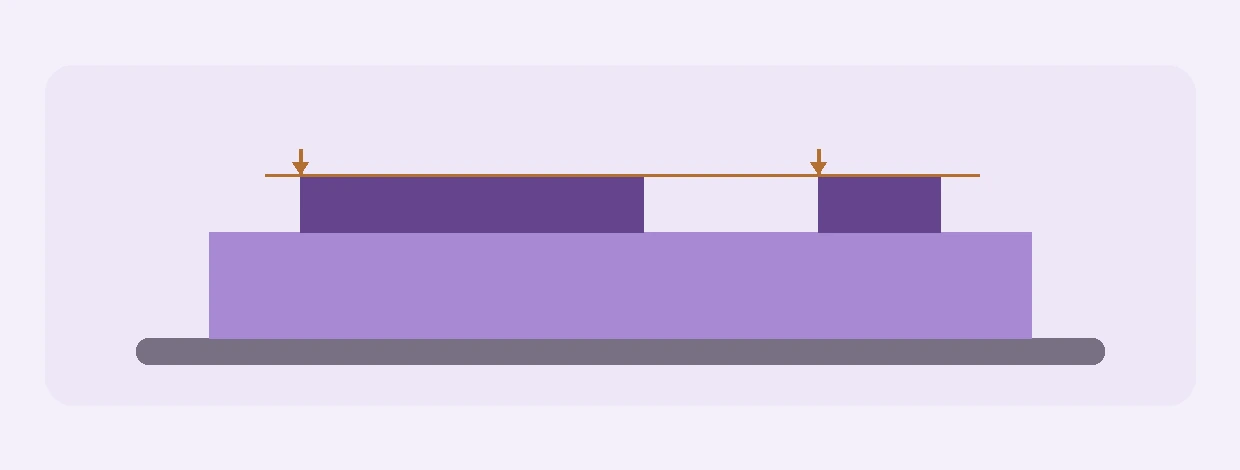
- Check scale and first-layer contact. Confirm the slicer reports a 30 × 24 mm footprint and a 5.5 mm model height before slicing. Inspect the first layer for a continuous base.
- Check the top toolpaths. Move the layer slider to the relief. The shaft should remain connected to the arrowhead, the dot should have its own toolpath, and the gap should stay clear. Use the N4D guide to designing your own 3D prints for the broader CAD-to-slicer workflow.
- Print one sample. After removal, inspect the raised surfaces under side lighting for ridges, strings, or high spots. Put the base on a flat block to support it during the ink test.
Printing face up makes the model straightforward to support, but the top toolpath can leave a texture on paper. Prusa’s tests found that a smooth build surface helped when the stamping surface was printed face down. Their FFF samples used high infill, around 60%, because low infill can show through the contact surface. If you try that method after inspecting your first impression, check the layer preview for portions of the base that would have to bridge between the raised features. A face-down version may need a redesigned plate or a different way to support it.
Step 4. Ink the Stamp and Check the Impression
Make the first impression on scrap paper. Tap the raised areas lightly on the ink pad. Set the stamp down vertically, press evenly on the back of the stamp, and lift it straight up. Make a second impression on another spot with the same motion to see whether the same defect repeats.
| What you see | What to check next |
|---|---|
| The arrow points left | Return to the face-on STL view. A right-pointing arrow there means the model needs one horizontal mirror. Check the dot changes sides while staying above the shaft. |
| One edge prints faintly | Rotate the stamp on a fresh scrap and repeat with the same backing and pressure. If the faint area follows the same edge of the mark, inspect that part of the face for uneven height or surface damage. |
| The dot merges with the arrow | Check the gap in the slicer’s top layers, then repeat with a lighter inking. If the gap is narrow in the toolpaths, widen it in the model. |
| A rectangle appears around the mark | Inspect the base near the edges for ink. If the base touches the pad or paper, try lighter pressure and firmer backing. If contact persists, revise the relief or base support and print a new sample. |
Keep the two scraps and write down the filament, orientation, and ink used. Change one thing at a time when you make another impression. Once the arrow points right, the dot is separate, and neither the base nor the layer pattern leaves an unwanted mark, try the stamp on the paper you will use for the project.
Common Questions About How to Make a 3D Printed Stamp
How do I use an existing logo for the stamp?
Start with artwork you can use, simplify it to one color, and turn the parts that should carry ink into closed vector outlines. Inspect tiny holes and fine gaps at actual stamp size. For a detailed logo, use a tool that accepts an SVG and lets you inspect the exact outlines. Prusa describes an SVG workflow in PrusaSlicer. Check whether your tool already mirrors the artwork before applying a reflection yourself.
Why does the print show parallel lines from the stamp surface?
Make a fresh impression with light inking. If evenly spaced lines still follow the same direction when you rotate the stamp, inspect the raised surface under side lighting and compare the lines with the slicer’s final layer. If the pattern matches, try a small sample with a different top-surface setting or a smooth face-down contact surface, after checking how the base will be supported.
Conclusion
Start with the arrow-and-dot sample. Check the mirrored relief in the exported STL, then print one flexible sample and make two impressions on scrap paper. Use the results to decide whether to adjust the model, the slicing setup, or how you ink and press the stamp. Once you can reproduce the intended mark, repeat the same checks with your own artwork.