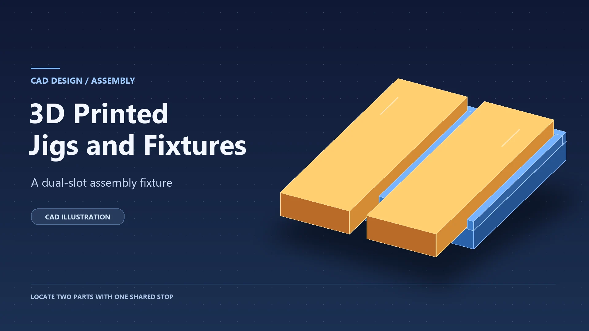
3D Printed Jigs and Fixtures: Build a Simple Assembly Fixture
When you lay two flat strips on a bench, it takes one adjustment to set the gap and another to bring their ends flush. Move either strip and you may have to do both again. A simple assembly fixture gives the strips the same surfaces to sit against each time. In this design, two shallow slots support the parts, a center divider sets the gap, and a shared stop lines up their ends. We used Coala to model the fixture and checked the exported STL. The print and fit checks below show how to validate it with your own parts.
What Are 3D Printed Jigs and Fixtures?
A drill jig guides a drill bit to a location on a workpiece. An assembly fixture positions the workpiece so you can carry out the same operation in the same place each time. The dual-slot design below is a fixture. You place the strips in it by hand and seat them against the same faces on every load. For other applications, see Stratasys’s guide to jigs and fixtures.
For this build, have two rigid, straight-edged strips, a caliper or suitable gauges, access to Coala, and an FDM printer with a slicer. Use the example for light bench assembly at room temperature. The design locates parts under light hand pressure.
Step 1. Define What the Fixture Must Control
Measure each strip’s length and thickness and take width measurements near both ends and at the middle. Check that the inside edges are straight enough to seat against the divider and that the ends can contact the stop. Use the widest reading for each strip when deciding how much room its slot needs. Write down the target gap, acceptable gap range, and maximum end offset before designing the fixture.
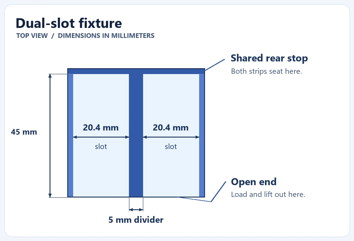
In the example, both strips are nominally 60 × 20 × 5 mm. Each 20.4 mm slot gives a 20 mm strip 0.4 mm of total loading clearance. After loading, push each strip gently inward against the 5 mm divider so that any remaining play is on the outside. Then seat both strips against the shared stop. The 45 mm slot length leaves 15 mm of each nominal strip projecting beyond the open end for removal.
These are design inputs for this example. Use your measured widths and a short printed sample to choose clearance for your parts and printer. Keep the divider low enough to let a gauge reach the inside edges of the seated strips. Formlabs describes the role of accessible reference faces in its guide to printed manufacturing aids.
Step 2. Model the Locating Slots in Coala
Open Coala, N4D’s AI CAD agent, and use CAD mode to describe the base and the three locating features. Specify the net slot width, the distance from the opening to the inside face of the rear stop, and which sides must remain open. This is the prompt used for the example model.
Create a one-piece CAD model of a dual-slot assembly fixture. Use millimeters. Make a flat rectangular base 49.8 mm wide, 47 mm long, and 4 mm thick. On top, create two parallel channels, each 20.4 mm wide and 45 mm long, with a 5 mm wide center divider and two 2 mm thick outer rails. The divider and rails rise 2 mm above the base. Leave the front and top of both channels open. Add a shared rear stop across the full base width, 2 mm thick and 2 mm high above the base. Both channels must end at the same inside face of the stop, 45 mm from the open front edge. Use square corners and flat surfaces. Merge the base, rails, divider, and stop into one solid and export it as STL.
Coala generated the model and listed an STL for download. The Properties panel showed a shared channel width and a separate divider width, along with the base dimensions and stop thickness. If you adapt the design, review how the values fit together. For example, the overall width is the sum of both slot widths, both rail widths, and the divider. After changing any dimension, recheck the geometry and export a fresh STL.
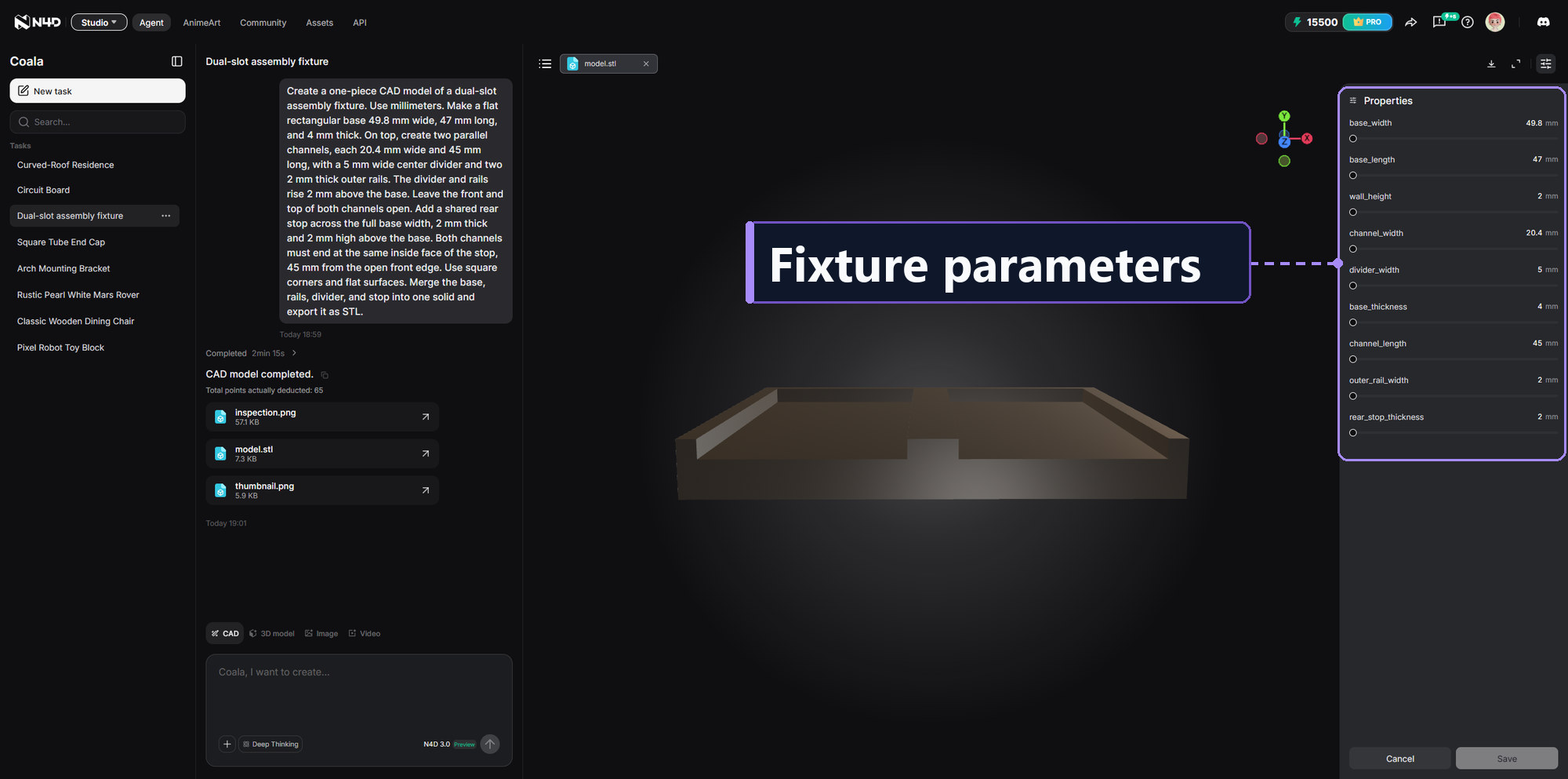
Measure the exported file in a tool that can inspect its mesh. Use millimeters and take widths between the opposing inside faces. Measure each slot at both ends or inspect the wall planes along the full length. The example STL matched the requested geometry:
| Feature | Measured in the mesh |
|---|---|
| Slot widths | 20.4 mm in each slot, constant from the open edge to the stop |
| Center divider | 5 mm wide |
| Shared rear stop | Both inside faces 45 mm from the open edge. Stop thickness 2 mm, height 2 mm above the slot floor. |
| Overall size | 49.8 × 47 × 6 mm (width × length × height), with a 4 mm base |
Step 3. Slice and Print a Slot Fit Sample
Before committing to the full length, make a short section that preserves the base thickness, both slots, the divider, and the rail heights. A 12 mm section from the open end is one starting point. Use your slicer’s cut tool if it can keep a closed section, or model a shortened copy. This sample checks the slot cross-section. The full print is where you check the rear stop and flatness over the working length.
- Import at the intended millimeter scale and place the flat base on the build plate with the slots facing up. Use the same orientation, material, and slicer settings for the sample and full fixture. For the general import workflow, see how to check an STL in your slicer.
- Inspect the layer preview where the walls rise from the base. Check that both slots remain open and that the toolpaths form continuous rails and a divider. Review the rear stop on the full model before printing it.
- Let the sample cool. Set both strips into the slots, seat them gently against the divider, and lift them out. Check for rocking, tight spots, or a raised edge that keeps a strip from sitting flat.
- If a strip binds, locate the contact point and measure the printed slot there. Check for a local burr before widening a slot. If the slot is consistently too narrow, change its width while keeping the divider faces at the intended gap, then print the sample again.
Step 4. Check Repeatability With Real Parts
Print the full fixture once the short sample fits. Let it cool, then check that the base sits flat and that the locating faces are clear of debris. Mark two gap measurement points on the strips, one near the open end and one near the stop, where the gauge can reach the edges above the divider. Decide how you will measure end offset. If the strips project above the stop, hold a straightedge across their rear end faces and measure any gap with a feeler gauge. You can also compare the exposed ends with a small square when both strips have the same measured length.
- Place both strips on the slot floors. Press each gently toward the divider and then toward the rear stop. Use the same seating motion each time.
- Measure the gap at both marked points with a gauge that fits above the divider. Record the end offset and note any rocking, binding, or failure to reach the stop.
- Lift both strips out completely and repeat until you have five independent loadings. Compare all the readings with the limits you wrote down in Step 1. Five loadings are a starting check for this pair of workpieces.
If one end of the gap is consistently wider, check whether both strips contact the divider along its length and whether either strip or the printed base is warped. If the gap is consistent but the ends are offset, inspect the stop face and look for debris or an out-of-square end on a workpiece. Change one feature at a time and repeat the same check.
3D Printed Jigs and Fixtures FAQ
Can I reuse the same fixture for a new batch of parts?
Start with parts near the widest and narrowest sizes in the new batch. Check that the widest parts can reach the stop and that the narrowest parts still seat against the divider using your normal loading motion. Recheck the gap and end offset. If a part binds, compare its measured width with the slot. If it loads easily but sits in the wrong place, check which locating face it actually contacts before changing the CAD model.
How can I tell when a printed fixture needs to be replaced?
Keep the original measurements and a pair of reference parts that passed the first check. If alignment drifts, clean the slot floors, divider, and stop, then reload the reference pair and use the original measuring points. If the readings stay outside your acceptance limits, inspect the locating faces for wear, cracks, or distortion. Replace or revise the fixture, then repeat the original check before using it again.
Conclusion
Coala produced an STL with both slots, the divider, and the stop at the requested dimensions. To adapt the design, start by measuring the widest point of each real workpiece and writing down the gap you want to hold. Turn those numbers into a short slot sample first. Once it fits, use the full print and repeated loadings to check that the gap and end alignment stay within your limits.